


 简体中文
简体中文 English
 Spanish


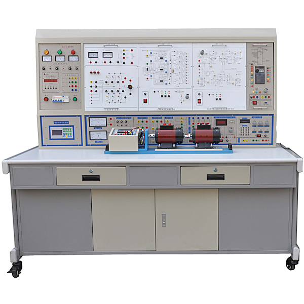
"Electric Drag Motion Control System Experimental Device" is based on the latest unified textbooks for colleges and universities "Power Electronics Technology" (Fifth Edition) (edited by Wang Zhao'an of Xi'an Jiaotong University) and "Electric Drag Automatic Control System" (Third Edition) (Compiled by Chen Boshi of Shangh* University) and other experimental syllabus requirements, absorbed the advantages of similar products at home and abroad, fully considered the current situation and development trends of the laboratory , and was carefully developed. Among similar products, it has reasonable structure, complete functions, good reliability and high cost performance.
2. Characteristics
1. Strong comprehensiveness: This device integrates current experimental projects such as power electronics, semiconductor converter, AC and DC speed regulation, AC frequency conversion, motor control, and control theory from various domestic schools.
2. Strong adaptability: It can satisfy the experimental teaching of corresponding courses in various schools. The depth and breadth can be flexibly adjusted according to needs. Popularization and improvement can be organically combined according to the teaching process. The device adopts a building block structure and is easy to replace, such as When you need to expand functionality or develop new experiments, just add parts and never become obsolete.
3. Strong complete set: from special power supply, motor and other experimental components to special wires for experimental connection, the performance and specifications of the supporting components are closely combined with the needs of the experiment.
4. Strong intuitiveness. Each experimental pendant adopts a separated structure, with clear component panel diagrams and clear diagrams. Each pendant has clear tasks and is easy to operate and m*nt*n.
5. Strong scientific nature: The device occupies a small area, saving experimental space and reducing infrastructure investment; the supporting small motors are specially designed to simulate the characteristics and parameters of small and medium-sized motors; small motors consume less power, save energy, and experiment It is low-noise, neat and beautiful, and improves the experimental environment; the experiment content is rich and the design is reasonable. In addition to deepening theoretical knowledge, it can also set up design experiments based on actual practice.
6. Strong openness: The power supply of the control panel is isolated by a three-phase isolation transformer, and is equipped with a voltage-type leakage protection device and a current-type leakage protection device to ensure the safety of the operator; each power output has monitoring and short-circuit protection functions. It is safe and reliable to use; the control panel is also equipped with a timer and alarm recorder, providing a unified standard for the assessment of students' experimental skills. Because the entire device has been carefully designed, coupled with reliable component quality and reliable technology as a guarantee, the product performance is excellent, all of which create conditions for an open laboratory.
7. Advanced nature: This device focuses on considering the height of new devices. On the basis of ret*ning the thyristor experiments, it adds a large number of modern power electronics technology experiments on the characteristics of new devices, new device drivers and typical new device applications, allowing Students have sufficient knowledge and understanding of new devices and keep up with the times.
3. Scope of application
This device covers "power electronics technology (or semiconductor inverter technology)", "DC speed regulation", "AC speed regulation", "motor control", and "electric drive automatic control system" established by various colleges and universities. " and "Control Theory" and other professional courses required experimental projects.
4. Technical performance
1. Input power supply: three-phase four-wire (or three-phase five-wire 380V±10% 50HZ)
2. Working environment: Temperature -10℃-+40℃ Relative humidity <85% (25℃) Altitude <4000m
3. Device capacity: <1.5KVA
4. Overall dimensions: 187×70×158cm3 (a 2.1-meter-long and 80-cm-wide table can also be customized according to customer requirements to facilitate placement of the oscilloscope)
5. Basic equipment of the device
1. DK01 power control panel (iron double-layer matt dense pattern spray-p*nted structure, aluminum panel)
(1) AC power supply (all with overcurrent protection measures)
AC power supply provided: DC speed adjustment gear is three-phase AC 200V/3A.
The AC speed control gear is three-phase AC 240V/3A.
(2) High voltage DC power supply
Excitation power supply: 220V (0.5A), with output short circuit protection.
(3) Instructions and measuring instruments
1. AC digital voltmeter: It can be switched through the band switch below to indicate the three-phase power grid input line voltage, with an accuracy of 1.0 level;
2. A true RMS AC digital voltmeter: measuring range 0~500V, automatic range judgment and automatic switching, accuracy level 0.5, three and a half digit display, providing voltage indication for the AC speed control system;
3. A true RMS AC digital ammeter: measuring range 0~5A, automatic range judgment and automatic switching, accuracy 0.5 level, three and a half digit display, with over-range alarm and indication functions, providing current indication for the speed control system;
4. A DC digital voltmeter: measuring range 0~500V, three-and-a-half-digit display, input impedance 10MΩ, accuracy level 0.5, providing voltage indication for the speed control system;
5. A DC digital ammeter: measuring range is 0~5A, three-and-a-half-digit display, accuracy level 0.5, providing current indication for the speed control system.
(4) Personal safety protection system
A set of three-phase isolation transformers: The three-phase power supply first passes through the three-phase leakage protector, and then passes through the key switch and contactor to the isolation transformer to isolate the output from the power grid (floating design), which plays a cert*n protective role in personal safety.
Current-type leakage protection device: If there is leakage in the control panel and the leakage current exceeds a cert*n value, the power supply will be cut off.
Voltage leakage protection device: If there is leakage on the control panel, the power supply will be cut off.
Experimental connection cables and sockets: Strong and weak current connections and sockets are separated and cannot be mixed.
The strong current connecting wires and sockets adopt fully enclosed technology, which is safe, reliable and prevents electric shock.
(5) Experiment manager
It has functions such as setting experiment time, timing alarms, cutting off power, etc. It can also automatically record and distinguish leakage alarms, instrument over-range alarms, etc. caused by wiring or operation errors.
(6) Control panel and other facilities
There are two steel pipes in the large groove on the front of the control screen, which can be used to hang experimental components. There are 3-pin sockets at the bottom of the groove. The power supply of the pendant is provided by these sockets. There are single-phase three-pole 220V power sockets and three-phase four-pole 380V power sockets on both sides of the control panel. There is also a 40W fluorescent lamp for experimental bench lighting.
2. DK02 experimental table
The experimental table is made of iron with a double-layer matt dense spray-p*nted structure. The tabletop is made of fireproof, waterproof and wear-resistant high-density board. It has a solid structure and is shaped like a rectangular closed structure. It has a beautiful and elegant appearance; it is equipped with two large drawers and cabinet doors. , used to place tools, store pendants and information, etc. The desktop is used to install the power control panel and provide a spacious and comfortable work surface. The experimental table is also equipped with four universal wheels and four fixed adjustment mechanisms, which are easy to move and fix, and are conducive to the layout of the laboratory.
3. DQ03-1 fixed motor guide r*l, tachometer generator and intelligent digital display tachometer
4. DQ27 three-phase adjustable resistor (900Ω×2/0.41A per group)
5. DK03 thyristor m*n circuit
Provides 12 5A/1000V thyristors. Each thyristor is equipped with RC absorption and fuse protection devices. The thyristor can be triggered by an external trigger signal (a trigger pulse input interface is left), which can better complete design experiments. It is equipped with a precision pointer DC voltmeter with a mirror of ±300V, a DC ammeter with a mirror accuracy of ±2A with an accuracy of 1.0, and a set of smoothing reactors with an accuracy of 1.0.
6. DK04 three-phase thyristor trigger circuit
Provide three-phase trigger circuit, power amplifier circuit, pulse transformer, etc., for use with "DK03".
7. DK06 motor speed control experiment (Ⅰ)
The following modules are provided: current feedback and overcurrent protection (FBC+FA), given device (G), speed converter (FBS), speed regulator (ASR), signal inverter (AR), current regulator (ACR) w*t
8. DK10 adjustable resistor and capacitor box
Provides three sets of adjustable capacitors with a voltage of AC63V, with an adjustment range of 0.1~11.37µF, and two sets of decimal adjustable resistors of 0~999kΩ; used for current regulator and speed regulator feedback loops, which can flexibly change the amplification factor of the regulator and Integration time.
9. DK12 transformer experiment
Provide a three-phase core transformer (the transformer has 2 sets of secondary windings, the voltage of the primary and secondary windings is 127V/63.6V/31.8V), used for asynchronous motor cascade speed regulation experiments and three-phase bridge, single Phase bridge active inverter circuit experiment; there are also modules such as three-phase uncontrolled rectifier circuit.
10. DK14 single-phase AC and DC frequency conversion principle
It is developed based on the content of "Power Electronics Technology" (Fourth Edition), a national key textbook for general higher education during the "Ninth Five-Year Plan" edited by Wang Zhaoan and Huang Jun. It is used to demonstrate the principle of AC-AC frequency conversion. It m*nly allows students to understand the formation method of SPWM sine wave pulse width modulation signal, understand the characteristics and use of IGBT tube-specific integrated driver chips, and be able to complete the following experimental projects:
1) The process of SPWM wave formation;
2) The working conditions and waveforms of AC, DC and AC frequency conversion circuits under different loads (resistance, inductance), and study the impact of operating frequency on the circuit’s operating waveform;
3) Working characteristics of IGBT tube dedicated integrated driver chip.
11. DK17 double closed-loop H-bridge DC/DC conversion DC speed control system
By triggering and controlling the IGBT tubes on the four bridge arms, the speed regulation of the reversible DC separately excited motor is achieved. It m*nly consists of three parts, namely the m*n loop part, the control circuit part and the adjustment part. The m*n loop is composed of DC power supply and four types of IGBT tubes; the control loop part uses a special chip to generate PWM pulse waves, and the four control pulses generated by the PWM wave pulse generator drive the IGBT tubes of the four bridge arms respectively; the adjustment part consists of two It is composed of a PI regulator, and through the feedback loop composed of speed loop and current loop, the motor speed can be stably run at a given speed. The experimental projects that this experimental box can complete include: (1), full-bridge DC/DC conversion circuit experiment (2), double closed-loop reversible DC pulse width speed regulation experiment.
12. DK06-1 motor speed control circuit (II)
The following modules are provided: zero-level detection (DPZ), torque polarity identification (DPT), and logic control (DLC).
13. DQ07-1 DC generator (DC220V, 240W)
14. DQ09 DC shunt motor (Un=DC220V, IN=1.1A, PN=185W, n=1500RPM, insulation grade E)
15. DQ11 three-phase wire-wound asynchronous motor (AC220V, connection Y, speed 1380RPM, power 120W, current 0.6A, insulation grade E)
16. GDQ12 wire-wound asynchronous motor starting and speed regulating resistor box
Provides a set of rotor starting and speed regulating resistors for three-phase wound asynchronous motors with five-speed coaxial adjustment of 0, 2, 5, 15 and 35.
17. SVPWM frequency converter speed regulation system
Provide 1 industrial frequency converter (single-phase 220V power supply, 0.4KW), which adopts a dedicated DSP motor m*n control IC, voltage vector control, and pure SVPWM output; the m*n circuit IPM module is the core component of the power drive, with built-in overcurrent, short circuit, and overload protection. Various reliable protections including temperature, extremely low f*lure rate; output frequency range from 0.1-400HZ, accuracy: 0.1HZ.
18. Experimental connection line:
According to the characteristics of different experimental projects, two different experimental connection lines are equipped. The high-power part adopts a high-reliability sheathed structure pistol plug connection line (there is no possibility of electric shock), and the inside is made of oxygen-free copper to make it look like h*r. The thin multi-stranded wire is ultra-soft and covered with a nitrile polyvinyl chloride insulation layer, which has the advantages of softness, high voltage resistance, high strength, anti-hardening, and good toughness. The plug is made of solid copper and is coated with beryllium light copper shrapnel. , the contact is safe and reliable; the weak current part adopts elastic beryllium light copper exposed structure connecting wire. Both wires can only match the sockets with corresponding inner holes, which greatly improves the safety and rationality of the experiment.
19. Teaching software
1. Electrical safety and electric shock first *d simulation teaching software
The software uses a combination of two-dimensional and three-dimensional virtual images to teach students the safety and first *d methods of using electricity. The software includes single-phase electric shock, two-phase electric shock, step electric shock, low-voltage electric shock first *d, high-voltage electric shock first *d, artificial respiration first *d, Principles of hand-holding breathing rescue method, chest cardiac compression and other protective methods are expl*ned and taught. Principles of single-phase electric shock are divided into rep*ring live disconnection, rep*ring socket electric shock, and outdoor electric shock. The teaching of low-voltage electric shock and high-voltage electric shock m*nly expl*ns and demonstrates to students how to rescue people who are suffering from low-voltage electric shock or high-voltage electric shock. Artificial respiration rescue method, hand-holding breathing rescue method, and chest cardiac compression rescue method are demonstrated using 3D virtual simulation technology. After rendering and Polish it to make the model look like the real part and look realistic. Through practical tr*ning, students can be educated on the safe use of electricity in the tr*ning room, improve students' safety awareness, and enable students to learn some self-rescue methods, so that students can take cert*n safety measures to protect themselves when encountering danger, and become familiar with various Causes of electrical accidents and practical measures to deal with them to reduce the occurrence of electrical accidents.
2. M*ntenance of electricians , electronic motors and vocational qualification tr*ning assessment simulation software
This software is in apk format and can be used on PC or mobile. This software can set faults manually or automatically. This software can manually set fault points through the green box in the circuit diagram (you can set up to 39 fault points), you can also automatically set one random fault point, two random fault points, three random fault points, four random fault points, and five random fault points through the system. It has functions such as toolbox, component library, magnifying glass, circuit diagram, etc. You can choose a multimeter for testing through the toolbox, select appropriate components through the component library, and clearly understand each component and circuit through the magnifying glass. This software allows students to understand the working principle and circuit structure of the motor star-delta start control circuit through the setting of faults in the motor star-delta start control circuit and various investigations.
3. Virtual spectrum analyzer, logic analyzer, oscilloscope, and three-meter simulation software:
This software is in apk format and can be used on PC or mobile terminals. The functions of this software are: resistance measurement, AC voltage measurement (measuring transformer, if the multimeter burns out when measuring the transformer, black smoke will emit prompts and can reset the multimeter), determine the polarity of the transistor, measure the DC voltage (the light turns on when the ammeter is turned on), measure the DC current, and determine the quality of the capacitor. This software can drag the red and black pen tips at will. When the two pen tips are dragged and positioned on the measured object, a red circle will be displayed. If the positioning is not accurate, no red circle will be displayed, and when incorrect operations are performed (such as the wrong range selected, If the measured data is wrong, etc.), the meter pointer will not respond, prompting errors and re-measurement, etc. This multimeter can select AC voltage range, DC voltage range, resistance range, current range, resistance adjustment to 0, and can enlarge the display data. Clearly view the measured data size. Students can learn the correct use of multimeters through this software.
4. Microcontroller and plc programmable design and control virtual simulation software:
This software is developed based on unity3d and has built-in experimental steps, experimental instructions, circuit diagrams, component lists, connection lines, power on, circuit diagrams, scene reset, return and other buttons. After the connections and codes are correct, you can start/stop, The forward movement and reverse movement buttons operate the 3D machine tool model to move. In the connected line state, the 3D machine tool model can be enlarged/reduced and translated.
1. Relay control: Read the experiment instructions and enter the experiment. By reading the circuit diagram, select the relays, thermal relays, switches and other components in the component list and drag and drop them into the electrical cabinet. The limiters are placed in the three-dimensional On the machine tool model, you can choose to cover it, and some component names can be renamed. Then click the Connect Line button to connect terminals to terminals. After successfully connecting the machine tool circuit, choose to turn on the power and proceed. If the component or line An error box will pop up if there is a connection error, and the scene can be reset at any time.
2. PLC control: The experiment is the same as relay control, with the addition of PLC control function. After the connection is completed, enter the program writing interface through the PLC coding button, and write two programs, forward and reverse, with a total of 12 ladder diagram symbols. The writing is completed. Finally, select Submit for program verification. After the verification is successful, turn on the power for operation. Error boxes will pop up for component, line connection, and code errors, and the scene can be reset at any time.
3. Single-chip microcomputer control: The experiment is the same as relay control, with the addition of single-chip microcomputer control function. After the connection is completed, enter the programming interface through the C coding button, enter the correct C language code, and after successful submission and verification, turn on the power for operation, components, lines If there are connection or code errors, an error box will pop up, and the scene can be reset at any time.
6. Experimental projects that can be set up by this device
(1) Power electronics technology experimental projects
1. Three-phase half-wave controllable rectifier circuit experiment
2. Three-phase bridge semi-controlled rectifier circuit experiment
3. Three-phase half-wave active inverter circuit experiment
4. Three-phase bridge type fully controlled rectifier and active inverter circuit experiment
5. Single-phase AC voltage regulating circuit experiment
6. Three-phase AC voltage regulating circuit experiment
(2) Typical power electronic device circuit experiments
1. Single-phase sine wave pulse width modulation (SPWM) inverter circuit experiment
2. Full-bridge DC/DC conversion circuit experiment
(3) DC motor speed regulation experiment (DC motor motion control system)
1. Debugging of parameters and m*n units of thyristor DC speed regulation system
2. Experiment on speed single closed-loop DC speed regulation system with current cutoff negative feedback
3. Experiment on speed and current double closed-loop DC speed regulation system
4. Logic circulation-free reversible DC speed control system experiment
5. Speed and current double closed-loop reversible DC pulse width modulation PWM speed control system (H-bridge, IGBT)
(4) AC motor speed control system experiment (AC motor motion control system)
1. Experiment on double closed-loop three-phase winding asynchronous motor voltage and speed regulation system
2. Experiment on double closed-loop three-phase wound asynchronous motor series pole speed regulation system
3. Experiment on frequency conversion and speed regulation of three-phase asynchronous motor based on DSP space voltage vector modulation SVPWM inverter.
7. Device configuration list
|
serial number |
serial number |
name |
quantity |
Remark |
|
1 |
DK01 |
Power control panel |
1 item |
|
|
2 |
DK02 |
Experiment table |
1 piece |
|
|
3 |
DQ03-1 |
Motor guide r*l, tachometer generator and digital tachometer |
1 item |
|
|
4 |
DQ27 |
Three-phase adjustable resistor (900Ω*2/0.41A per group) |
1 item |
|
|
5 |
DK03 |
Thyristor m*n circuit |
1 item |
|
|
6 |
DK04 |
Three-phase thyristor trigger circuit |
1 item |
|
|
7 |
DK06 |
Motor speed control experiment (Ⅰ) |
1 item |
|
|
8 |
DK10 |
Adjustable resistor and capacitor box |
1 item |
|
|
9 |
DK12 |
Transformer experiment |
1 item |
|
|
10 |
DK14 |
SPWM single-phase AC and DC frequency conversion principle |
1 item |
|
|
11 |
DK17 |
Double closed-loop H-bridge DC/DC converter speed control system |
1 item |
|
|
12 |
DK06-1 |
Motor speed control system (Ⅱ) |
1 item |
|
|
13 |
DQ07-1 |
DC generator (220W) |
1 set |
|
|
14 |
DQ09 |
DC separately (parallel) excited motor |
1 set |
|
|
15 |
DQ11 |
Three-phase wire-wound asynchronous motor |
1 set |
|
|
16 |
GDQ12 |
Special box for wirewound asynchronous motor rotor |
1 item |
|
|
17 |
BP |
Frequency converter speed control system |
1 item |
|
|
18 |
Highly reliable sheath structure pistol plug experimental connection cable and accessories |
1 set |
||
|
19 |
Guiding book |
Experiment instructions |
1 set |
Hot-selling product: Electrician tr*ning bench
欢迎咨询YLDDZS-1 Electric Power Drag Motion Control System Experimental Device相关问题,我们是源头工厂,有标准工业厂房生产基地,欢迎前来考察,如有YLDDZS-1 Electric Power Drag Motion Control System Experimental Device其他问题,可联系19957812178
