


 简体中文
简体中文 English
 Spanish


Product 

1. Product Overview
This product is developed based on the Ministry of Education's "Digital Campus Construction Specifications for Vocational Education" and the People's Republic of China Labor and Labor Safety Industry Standard (LD/T81.1-2006) "General Technical Specifications for Vocational Skills Tr*ning and Identification Equipment", and the Ministry of Education and the Ministry of Human Resources and Social Security's relevant professional teaching syllabus, in order to alleviate the deficiencies of traditional experimental tr*ning teaching links in elevator majors and improve students' professional skills. This software uses the German Thyssen-Krupp vertical elevator as a physical model to conduct simulation tr*ning on its installation and typical troubleshooting. The content includes construction preparation, sample frame laying, guide r*l installation, speed limiter installation, control cabinet installation, floor door installation, call board installation, traction machine installation, buffer installation, counterweight installation, car installation, car door installation, wire rope installation, fault troubleshooting 1, 2, 3, etc., a total of 16 simulation tr*ning projects, each tr*ning unit cont*ns several tr*ning projects, and each tr*ning project cont*ns several typical tr*ning steps.
The software takes actual engineering projects as the m*n line, construction tasks as the guide, and highlights skill tr*ning; it emphasizes the working environment of the workplace, and all tr*ning is carried out in a three-dimensional scene; it attaches importance to teaching design, and different knowledge units cont*n practical tr*ning modules such as installation must-read, technical specifications, safety disclosure, relevant materials, teaching resources, project progress, construction preparation, etc.
The software is made using three-dimensional visualization control and database technology, and has strong technical, professional, situational, procedural and interactive characteristics. The software has operation prompts for learners to simulate tr*ning by themselves.
This software integrates situational teaching and interactive tr*ning functions, and plays a major role in "information technology has a revolutionary impact on educational development". It will play an irreplaceable role in accelerating the realization of informatization and modernization of teaching and practical teaching of motor and electrical assembly and m*ntenance, and solving or alleviating many problems in professional internships such as motor and electrical assembly and m*ntenance.
2. Software Features
The software is m*nly based on 3D visualization control technology, focusing on incorporating production tr*ning into the workplace environment, conforming to the characteristics of vocational education, and has good situational characteristics; the content comes from the typical production site of the occupation (type of work), focusing on the standardized tr*ning of the operation process, and providing drawings, production processes, industry specifications, the use of tools and equipment, safe production and other internship and tr*ning resources. Through dynamic interaction with the software, students can select machines, answer questions and other links, so that students can feel as if they are in the actual construction project, combining learning and practice.
The software adopts full 3D programming technology, 3D animation under fixed scenes and 2D programming technology to effectively compress data and occupy a small data space. After testing, the response time of the software does not exceed 1 second at most, and the running speed meets the standard. The continuous broadcast function is supported during the operation, and the interactive construction steps can be played continuously. The software is click-to-use, and the response speed is less than or equal to 1 second, which is convenient for teachers to expl*n the knowledge content synchronously during teaching and enables students to deepen their memory and consolidate their learning. The
system has strong interactivity, simple and convenient operation, and flexible and reliable use. The software has rich media means and reasonable application.
欢迎咨询YL Elevator Installation Simulation Training Device相关问题,我们是源头工厂,有标准工业厂房生产基地,欢迎前来考察,如有YL Elevator Installation Simulation Training Device其他问题,可联系19957812178
This product is developed based on the Ministry of Education's "Digital Campus Construction Specifications for Vocational Education" and the People's Republic of China Labor and Labor Safety Industry Standard (LD/T81.1-2006) "General Technical Specifications for Vocational Skills Tr*ning and Identification Equipment", and the Ministry of Education and the Ministry of Human Resources and Social Security's relevant professional teaching syllabus, in order to alleviate the deficiencies of traditional experimental tr*ning teaching links in elevator majors and improve students' professional skills. This software uses the German Thyssen-Krupp vertical elevator as a physical model to conduct simulation tr*ning on its installation and typical troubleshooting. The content includes construction preparation, sample frame laying, guide r*l installation, speed limiter installation, control cabinet installation, floor door installation, call board installation, traction machine installation, buffer installation, counterweight installation, car installation, car door installation, wire rope installation, fault troubleshooting 1, 2, 3, etc., a total of 16 simulation tr*ning projects, each tr*ning unit cont*ns several tr*ning projects, and each tr*ning project cont*ns several typical tr*ning steps.
The software takes actual engineering projects as the m*n line, construction tasks as the guide, and highlights skill tr*ning; it emphasizes the working environment of the workplace, and all tr*ning is carried out in a three-dimensional scene; it attaches importance to teaching design, and different knowledge units cont*n practical tr*ning modules such as installation must-read, technical specifications, safety disclosure, relevant materials, teaching resources, project progress, construction preparation, etc.
The software is made using three-dimensional visualization control and database technology, and has strong technical, professional, situational, procedural and interactive characteristics. The software has operation prompts for learners to simulate tr*ning by themselves.
This software integrates situational teaching and interactive tr*ning functions, and plays a major role in "information technology has a revolutionary impact on educational development". It will play an irreplaceable role in accelerating the realization of informatization and modernization of teaching and practical teaching of motor and electrical assembly and m*ntenance, and solving or alleviating many problems in professional internships such as motor and electrical assembly and m*ntenance.
| Tr*ning Unit | Project Process | Practical tr*ning module | model | Project Process Description | |
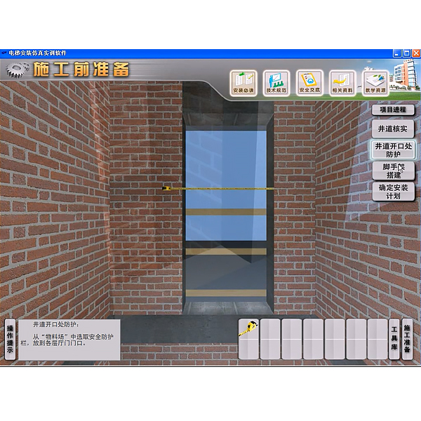
| Preparation before construction | Well verification |
Must-read for installation (installation process, installation manual, engineering drawing 1, engineering drawing 2, civil engineering technical requirements, traction machine installation and m*ntenance); technical specifications (elevator manufacturing and installation safety specifications, elevator engineering construction quality acceptance specifications, elevator pre-delivery site status confirmation form, project elevator installation schedule); safety briefing (site construction safety plan, site construction safety analysis); related materials (operation and m*ntenance manual); teaching resources (elevator knowledge PPT, teachers can add or modify relevant knowledge on their own); construction preparation (tool library, material library); operating tips; project progress; technical requirements; quick questions and answers. |
Text, pictures, 3D tr*ning |
Hoistway verification: The elevator hoistway is constructed by a professional construction team. Before installing the elevator, the size of the elevator hoistway must be checked. Before the start of this project, the technical requirements will pop up. The elevator hoistway is constructed by a professional construction team. Before installing the elevator, the size of the elevator hoistway must be checked. Select tools from the "Tool Library" according to the operation prompts, and measure and verify ag*nst the installation drawings (with simulated tool use sound effects). |
|
| Protection of shaft openings |
Protection of shaft openings: Technical requirements will pop up before the start of this project. Before the installation work begins, you need to confirm that guardr*ls have been installed at each shaft opening to prevent falling → Select the materials and tools to be used from the "Material Yard" and "Tool Library" to protect the shaft openings (with simulated tool use sound effects) → Quick Questions and Answers (What are the correct statements about installing guardr*ls) |
||||
| Scaffolding construction |
Scaffolding construction: Technical requirements will pop up before the start of this project. The construction party who builds and dismantles the scaffolding must have relevant qualifications, and the construction personnel must be certified and strictly abide by the relevant national construction regulations → Select the materials and tools to be used from the "material yard" and "tool library" for scaffolding construction (and there will be simulated tool use sound effects) → Technical requirements and quick questions (Do the relevant personnel who build the scaffolding have to have relevant qualifications) |
||||
| Determine the installation plan |
Determine the installation plan: Before the start of this project, the technical requirements pop up → This module has been completed, please return to the upper menu to continue learning other content. |
||||
| Sample rack laying out | Sample rack production |
Must-read for installation (installation process, installation manual, engineering drawing 1, engineering drawing 2, civil engineering technical requirements, traction machine installation and m*ntenance); technical specifications (elevator manufacturing and installation safety specifications, elevator construction quality acceptance specifications, elevator pre-delivery site status confirmation form, project elevator installation schedule); safety briefing (site construction safety plan, site construction safety analysis); related materials (operation and m*ntenance manual); teaching resources (elevator knowledge PPT, teachers can add or modify relevant knowledge on their own); construction preparation (tool library, material library); operating tips; project progress; technical requirements; quick questions and answers; technical instructions. |
Text, pictures, 3D tr*ning |
Sample frame production: The sample frame is a plumb line for fixing the hall door and guide r*l. The plumb line is a reference for the installation position of the hall door and guide r*l. Before the start of this project, the technical requirements will pop up. According to the cross-sectional dimensions of the elevator shaft, the wood for making the sample frame should be selected. The wood should be dry, not easy to deform, and able to withstand a cert*n weight. The wood must be smooth and str*ght, planed on all four sides, and at right angles to each other → Select the materials and tools to be used from the "material yard" and "tool library" to make the sample frame (and there are simulated tool use sound effects) → Technical operation instructions and quick questions and answers (Is there a fixed order for installing the sample frame?). |
|
| Sample rack Sample rack placement and plumb line hanging |
Sample rack installation and plumb line hanging: Select the materials and tools to be used from the "Material Yard" and "Tool Library" to install the sample rack and hang the plumb line (with simulated tool use sound effects) → Quick Questions and Technical Descriptions: Laying out the sample rack is an important basis for installing the hall door, car and counterweight r*ls. According to experience, 10 wires can meet the installation requirements. It is also possible to lay out more wires, for example, 12 wires: 2 for the hall door; 6 for the car r*ls; 6 for the counterweight r*ls. If the number of wires is too small, it will have a greater impact on the actual installation size, which should be avoided as much as possible. |
||||
| R*l installation | Note before construction |
Must-read for installation (installation process, installation manual, engineering drawing 1, engineering drawing 2, civil engineering technical requirements, traction machine installation and m*ntenance); technical specifications (elevator manufacturing and installation safety specifications, elevator construction quality acceptance specifications, elevator pre-delivery site status confirmation form, project elevator installation schedule); safety briefing (site construction safety plan, site construction safety analysis); related materials (operation and m*ntenance manual); teaching resources (elevator knowledge PPT, teachers can add or modify relevant knowledge on their own); construction preparation (tool library, material library); operating tips; project progress; technical requirements; pay attention to safety; quick questions and answers; technical instructions. |
Text, pictures, 3D tr*ning |
Note before construction: Technical requirements: The installation of guide r*ls and guide r*l brackets is an important part of the entire elevator installation. Safety attention signs remind. |
|
| Guide r*l bracket installation |
Installation requirements for guide r*l brackets: Technical requirements and engineering drawings → According to the shaft drawings, select the tools to be used from the "tool library" to determine the installation position of the guide r*l bracket (with simulated tool use sound effects) |
||||
| Installation of guide r*ls |
Install the guide r*l bracket: Select the materials and tools to install the guide r*l bracket from the "Material Yard" and "Tool Library" (with simulated tool use sound effects) → Quick Ask Express, Technical Requirements and Operation Drawings |
||||
| Layer selector blade installation |
Installation and adjustment of guide r*ls: Install the counterweight rope head plate on the load-bearing beam, and weld the rope head plate and the I-beam by manual arc welding → Select the materials and tools to be used from the "Material Yard" and "Tool Library" to install and adjust the guide r*ls (with simulated tool use sound effects) → Quick Q&A and det*led picture display → Select the materials to be used from the "Material Yard" to install the blade selector → Quick Q&A and technical requirements |
||||
| Speed limiter installation | to mark |
Must-read for installation (installation process, installation manual, engineering drawing 1, engineering drawing 2, civil engineering technical requirements, traction machine installation and m*ntenance); technical specifications (elevator manufacturing and installation safety specifications, elevator construction quality acceptance specifications, elevator pre-delivery site status confirmation form, project elevator installation schedule); safety briefing (site construction safety plan, site construction safety analysis); related materials (operation and m*ntenance manual); teaching resources (elevator knowledge PPT, teachers can add or modify relevant knowledge on their own); construction preparation (tool library, material library); operating tips; project progress; pay attention to safety; quick questions and answers. |
Text, pictures, 3D tr*ning |
Installation precautions: Select the materials and tools to be used from the "Material Yard" and "Tool Library" for marking → Quick Questions and Answers |
|
| drilling | Select a tool from the Tool Library to drill a hole (with simulated tool usage sound effects) | ||||
| Install |
Fix the speed limiter: Select expansion bolts from the "Material Yard" and fix the speed limiter base to the machine room floor. |
||||
| Control cabinet installation | Installation Precautions |
Must-read for installation (installation process, installation manual, engineering drawing 1, engineering drawing 2, civil engineering technical requirements, traction machine installation and m*ntenance); technical specifications (elevator manufacturing and installation safety specifications, elevator construction quality acceptance specifications, elevator pre-delivery site status confirmation form, project elevator installation schedule); safety briefing (site construction safety plan, site construction safety analysis); related materials (operation and m*ntenance manual); teaching resources (elevator knowledge PPT, teachers can add or modify relevant knowledge on their own); construction preparation (tool library, material library); operating tips; project progress; precautions; preparation of installation tools; quick questions and answers. |
Text, pictures, 3D tr*ning | Preparation of precautions. Safety signs such as beware of electric shock and protective gloves (in graphic form). | |
| Installation tools | Preparation of installation tools (in graphic form). | ||||
| Control cabinet installation | Select the materials and tools to be used from the "Material Yard" and "Tool Library" to install the control cabinet (with simulated tool use sound effects) → Quick Questions and Answers, Precautions and Operation Drawings | ||||
| Landing door installation | Pre-installation preparation |
Must-read for installation (installation process, installation manual, engineering drawing 1, engineering drawing 2, civil engineering technical requirements, traction machine installation and m*ntenance); technical specifications (elevator manufacturing and installation safety specifications, elevator construction quality acceptance specifications, elevator pre-delivery site status confirmation form, project elevator installation schedule); safety briefing (site construction safety plan, site construction safety analysis); related materials (operation and m*ntenance manual); teaching resources (elevator knowledge PPT, teachers can add or modify relevant knowledge on their own); construction preparation (tool library, material library); operating tips; project progress; installation identification instructions; preparation of installation tools; technical requirements; precautions; quick questions and answers. |
Text, pictures, 3D tr*ning |
Preparation before work: safety signs and preparation of installation tools. |
|
| Hall door sill installation | Confirm the technical requirements of the installation position → Assemble the door frame (mark the center line of the sill and the door width line) → Select the materials and tools to be used from the "Material Yard" and "Tool Library" to install the sill bracket and sill → Select the materials and tools to be used from the "Material Yard" and "Tool Library" to fix the sill bracket in the hoistway (with simulated tool use sound effects) → Calibrate the sill according to specific requirements → Install the hall door toeboard | ||||
| Hall door frame installation | Assemble the hall door frame → Install and fix the hall door frame → Fix the hall door frame to the wall → Measure and adjust the hall door frame size. This project unit selects the materials and tools to be used from the "material yard" and "tool library" to install the hall door frame (with simulated tool use sound effects) | ||||
| Hall door suspension assembly installation | Install the hall door suspension bracket → install the hall door suspension device → install the hall door suspension device and door pocket → adjust the hall door suspension device. This project unit selects the materials and tools to be used from the "material yard" and "tool library" to install the hall door suspension components (with simulated tool use sound effects, quick questions and answers, and technical requirements) | ||||
| Hall door leaf installation | Install the hall door panel and slider → adjust the hall door panel → adjust the eccentric wheel and hall door lock. This project unit selects the materials to be used from the "material yard" to install the hall door leaf. | ||||
| Installation of call board | Installation Precautions |
Must-read for installation (installation process, installation manual, engineering drawing 1, engineering drawing 2, civil engineering technical requirements, traction machine installation and m*ntenance); technical specifications (elevator manufacturing and installation safety specifications, elevator construction quality acceptance specifications, elevator pre-delivery site status confirmation form, project elevator installation schedule); safety briefing (site construction safety plan, site construction safety analysis); related materials (operation and m*ntenance manual); teaching resources (elevator knowledge PPT, teachers can add or modify relevant knowledge on their own); construction preparation (tool library, material library); operating tips; project progress; precautions; preparation of installation tools; quick questions and answers. |
Text, pictures, 3D tr*ning | Installation Notes: Preparation of notes (pictures and text). | |
| Installation tools |
Installation tools: Preparation of installation tools (pictures and text). |
||||
| installation method |
Installation method: Confirm the installation location according to the engineering drawings. This project unit selects the materials and tools to be used from the "material yard" and "tool library" to install the call board. |
||||
| Traction machine installation | Preparation before work |
Must-read for installation (installation process, installation manual, engineering drawing 1, engineering drawing 2, civil engineering technical requirements, traction machine installation and m*ntenance); technical specifications (elevator manufacturing and installation safety specifications, elevator construction quality acceptance specifications, elevator pre-delivery site status confirmation form, project elevator installation schedule); safety briefing (site construction safety plan, site construction safety analysis); related materials (operation and m*ntenance manual); teaching resources (elevator knowledge PPT, teachers can add or modify relevant knowledge on their own); construction preparation (tool library, material library); operating tips; project progress; precautions; preparation of installation tools; technical requirements; quick questions and answers; pay attention to safety. |
Text, pictures, 3D tr*ning |
Preparation before work: precautions, preparation of installation tools (pictures and text), and technical requirements. |
|
| Centerline marking of the equipment room | This project unit selects materials and tools from the "Material Yard" and "Tool Library" to mark the centerline of the machine room (with simulated tool use sound effects) | ||||
| Installation of traction machine load-bearing beam | This project unit selects the materials and tools to be used from the "material yard" and "tool library" to install the traction machine load-bearing beam (with simulated tool use sound effects and technical requirements) | ||||
| Traction machine installation | This project unit selects the materials and tools to be used from the "material yard" and "tool library" for traction machine installation (with simulated tool use sound effects, technical requirements, quick questions and answers) | ||||
| Buffer installation | Check the buffer before installation |
Must-read for installation (installation process, installation manual, engineering drawing 1, engineering drawing 2, civil engineering technical requirements, traction machine installation and m*ntenance); technical specifications (elevator manufacturing and installation safety specifications, elevator construction quality acceptance specifications, elevator pre-delivery site status confirmation form, project elevator installation schedule); safety briefing (site construction safety plan, site construction safety analysis); related materials (operation and m*ntenance manual); teaching resources (elevator knowledge PPT, teachers can add or modify relevant knowledge on their own); construction preparation (tool library, material library); operating tips; project progress; installation attention; technical requirements; installation precautions; quick questions and answers. |
Text, pictures, 3D tr*ning |
Inspection before buffer installation: Install according to drawings and national standards. |
|
| Buffer installation and adjustment |
Installation and adjustment of buffers: According to the drawings, select the materials and tools to be used from the "material yard" and "tool library" to install and adjust the buffers (with simulation tool use sound effects and technical requirements) |
||||
| Installation Precautions |
Notes on buffer installation: For the specific adjustment method of the buffer, please refer to the buffer manual and quick questions and answers. |
||||
| Counterweight installation | Counterweight frame installation |
Must-read for installation (installation process, installation manual, engineering drawing 1, engineering drawing 2, civil engineering technical requirements, traction machine installation and m*ntenance); technical specifications (elevator manufacturing and installation safety specifications, elevator engineering construction quality acceptance specifications, elevator pre-delivery site status confirmation form, project elevator installation schedule); safety briefing (site construction safety plan, site construction safety analysis); related materials (operation and m*ntenance manual); teaching resources (elevator knowledge PPT, teachers can add or modify relevant knowledge on their own); construction preparation (tool library, material library); operating tips; project progress; technical requirements; quick questions and answers. |
Text, pictures, 3D tr*ning | According to the drawings, select the materials and tools to be used from the "Material Yard" and "Tool Library" to install the counterweight frame (with simulated tool use sound effects, technical requirements, quick questions and answers, and operation drawings) | |
| Counterweight installation | Select the materials to be used from the "material yard" for counterweight installation (technical requirements, quick questions and answers) | ||||
| Counterweight guardr*l installation | Select the materials to be used from the "material yard" for counterweight guardr*l installation (quick questions and answers) | ||||
| Car installation | Car frame installation |
Must-read for installation (installation process, installation manual, engineering drawing 1, engineering drawing 2, civil engineering technical requirements, traction machine installation and m*ntenance); technical specifications (elevator manufacturing and installation safety specifications, elevator construction quality acceptance specifications, elevator pre-delivery site status confirmation form, project elevator installation schedule); safety briefing (site construction safety plan, site construction safety analysis); related materials (operation and m*ntenance manual); teaching resources (elevator knowledge PPT, teachers can add or modify relevant knowledge by themselves); construction preparation (tool library, material library); operating tips; project progress; technical requirements; quick questions and answers; precautions; debugging requirements. |
Text, pictures, 3D tr*ning |
The structure of the car frame and car: Introduction, technical requirements → Install the lower beam → Install the column → Install the upper beam → Install the tie rod → Install the safety clamp → Install the guide shoe → Install the oil cup → Install the vibration reduction device |
|
| Car installation | Install car bottom → hoist car top → install car wall → fix car top → install car top wheel → install car top guardr*l | ||||
| Installation of COP in car guard plate | Select the materials and tools to be used from the "Material Yard" and "Tool Library" to install the COP in the car | ||||
| Car accessories installation | Car top fan installation → Car top inspection box installation → Leveling sensor installation | ||||
| Car door installation | Car door sill installation |
Must-read for installation (installation process, installation manual, engineering drawing 1, engineering drawing 2, civil engineering technical requirements, traction machine installation and m*ntenance); technical specifications (elevator manufacturing and installation safety specifications, elevator engineering construction quality acceptance specifications, elevator pre-delivery site status confirmation form, project elevator installation schedule); safety briefing (site construction safety plan, site construction safety analysis); related materials (operation and m*ntenance manual); teaching resources (elevator knowledge PPT, teachers can add or modify relevant knowledge on their own); construction preparation (tool library, material library); operating tips; project progress; technical requirements; quick questions and answers. |
Text, pictures, 3D tr*ning | Select the materials and tools to install the car door sill from the "Material Yard" and "Tool Library" (Technical Requirements, Quick Questions and Answers) | |
| Car door footboard installation | Select the materials and tools to install the car door toeboard from the "Material Yard" and "Tool Library" (Technical Requirements, Quick Questions and Answers) | ||||
| Door machine component installation | Select the materials and tools to install the gantry crane components from the "Material Yard" and "Tool Library" (Technical Requirements, Quick Questions and Answers) | ||||
| Car door panel installation | Select the materials and tools to install the car door panels from the "Material Yard" and "Tool Library" (Technical Requirements, Quick Questions and Answers) | ||||
| Car door knife installation | Select the materials and tools to install the car door blade from the "Material Yard" and "Tool Library" (Technical Requirements, Quick Questions and Answers) | ||||
| Wire rope installation | Wire rope release |
Must-read for installation (installation process, installation manual, engineering drawing 1, engineering drawing 2, civil engineering technical requirements, traction machine installation and m*ntenance); technical specifications (elevator manufacturing and installation safety specifications, elevator engineering construction quality acceptance specifications, elevator pre-delivery site status confirmation form, project elevator installation schedule); safety briefing (site construction safety plan, site construction safety analysis); related materials (operation and m*ntenance manual); teaching resources (elevator knowledge PPT, teachers can add or modify relevant knowledge on their own); construction preparation (tool library, material library); operating tips; project progress; technical requirements; quick questions and answers. |
Text, pictures, 3D tr*ning | The installation process and method of laying out the wire rope, select the materials and tools to be used from the "material yard" and "tool library" to lay out the wire rope (technical requirements, quick questions and answers) | |
| Installation of wire rope and traction sheave groove | Select the materials and tools to install the wire rope and traction sheave groove from the "Material Yard" and "Tool Library" (Technical Requirements, Quick Questions and Answers) | ||||
| Installation of wire rope and rope head plate | Select the materials and tools to install the wire rope and rope head plate from the "Material Yard" and "Tool Library" (Technical Requirements, Quick Questions and Answers) | ||||
| Automatic wedge-shaped rope head assembly | Select the materials and tools to be used from the "Material Yard" and "Tool Library" to automatically tighten the wedge-shaped rope head assembly (technical requirements, quick questions and answers) | ||||
| Adjustment of wire rope tension | Select the materials and tools to adjust the wire rope tension from the "Material Yard" and "Tool Library" (Technical Requirements, Quick Questions and Answers) | ||||
| Post-installation inspection | Inspection precautions after installation. | ||||
| Troubleshooting | Overview | Analysis of common elevator f*lures | Text, pictures, 3D tr*ning | Analysis of common elevator faults (pictures and text) | |
|
Fault 1: Door not fully opened |
cause of issue |
Must-read for installation (installation process, installation manual, engineering drawing 1, engineering drawing 2, civil engineering technical requirements, traction machine installation and m*ntenance); technical specifications (elevator manufacturing and installation safety specifications, elevator construction quality acceptance specifications, elevator pre-delivery site status confirmation form, project elevator installation schedule); safety briefing (site construction safety plan, site construction safety analysis); related materials (operation and m*ntenance manual); teaching resources (elevator knowledge PPT, teachers can add or modify relevant knowledge on their own); construction preparation (tool library, material library); operation prompts; project progress; fault phenomenon. Virtual simulation teaching system mechanical tr*ning safety education virtual simulation software: This software is developed based on unity3d. The software adopts the form of three-dimensional roaming. The movement can be controlled by the keyboard and the direction of the lens can be controlled by the mouse. There are mechanical safety distance experiments, mechanical safety protection device experiments, and mechanical safety protection design basic assessments. During the experiment, the three-dimensional roaming screen uses arrows and footprints to prompt movement to the experimental position. The circle around the mechanical object shows the working radius. The experimental process is accompanied by a dialog box reminder of the three-dimensional robot. A. The content of the mechanical safety distance experiment includes the safety distance experiment to prevent the upper and lower limbs from touching the dangerous area (with two types of fence height and opening size). After entering, the GB23821-2009 "Safety distance to prevent the upper and lower limbs from touching the dangerous area" requirement pops up in front of the camera. Wrong demonstration: the experiment process is that after the human body enters the working radius of the mechanical object and is injured, the bloody picture and voice reminder receive mechanical injury, and return to the original position and conduct the next experiment. The last step is the correct approach. B. The mechanical safety protection device experiment is divided into safety interlock switch, safety light curt*n, safety mat, safety laser scanner and other protection device experiments. The optional categories (safety input, safety control, safety output, other), manufacturer, product list (safety interlock switch, safety light curt*n, safety mat, safety laser scanner, safety controller, safety relay, safety fence). There is a blue flashing frame reminder at the installation location. The experimental process: select the safety fence and install it, select the safety interlock switch (or select the safety light curt*n, safety mat, safety laser scanner) and install it, select the safety controller and install it to the electrical control box, select the safety relay and install it to the electrical control box, and click the start button on the electrical control box. If you enter the dangerous area, the system will prompt an alarm sound, and the mechanical object will stop working. You can stop by selecting the reset button on the electrical control box. C. The basic assessment of mechanical safety protection design requires the installation of the mechanical safety system to be completed, and the safety guardr*l, safety interlock switch, safety light curt*n, safety mat, safety laser scanner, safety controller, safety relay, 24V power supply, signal light and emergency stop button to be correctly installed. The assessment is divided into ten assessment points. Some assessment points have 3 options, which are freely selected by students. After the final 10 assessment points are selected, submit for confirmation, and the system automatically obt*ns the total score and the score of each assessment point. D. The software must be the same platform as a whole and shall not be displayed as a separate resource. E. At the same time, the VR installation package of this software is provided to customers to facilitate users to expand it into VR experiments. VR equipment and software installation and debugging do not need to be provided. Mechanical assembly and bench assembly virtual simulation software: This software is developed based on unity3d, with 6 levels of image quality optional, and has the design and virtual disassembly and assembly of reducers and shafting structures, design and simulation of common mechanical mechanisms , mechanism resource library, typical mechanical mechanisms (virtual disassembly and assembly of gasoline engines). The software is an overall software and cannot be a separate resource. A. Reducer design and virtual disassembly and assembly interface can choose worm gear bevel gear reducer, two-stage expanded cylindrical gear reducer, bevel cylindrical gear reducer, coaxial cylindrical gear reducer, bevel gear reducer, and one-stage cylindrical gear reducer. Worm bevel gear reducer: After entering the software, the assembly content will be automatically played, and each step in the video will be described in text. Secondary unfolded cylindrical gear reducer: After entering the software, the content will be played in the form of video. The video content should include: part name (scan the QR code to see the part name), disassembly demonstration (including disassembly, assembly), virtual disassembly (including the whole, low-speed shaft, medium-speed shaft, high-speed shaft, box cover, box seat) Bevel cylindrical gear reducer, coaxial cylindrical gear reducer, bevel gear reducer, first-level cylindrical gear reducer: click to enter and automatically jump to the edrawings interface. The models are all three-dimensional models. By clicking on the parts to display the part name, you can rotate 360° in all directions, zoom in, zoom out, and translate. At the same time, you can use the move parts function to disassemble and assemble the entire reducer. At the same time, you can select the home button to return to the original state of the reducer. The bevel gear reducer and the first-level cylindrical gear reducer have added the function of inserting cross sections, and the cross sections can be freely dragged to observe the internal structure of the reducer. B. The design of the shaft system structure and the virtual disassembly and assembly interface can select part recognition, disassembly and assembly demonstration, and actual combat operation. 1. Part recognition: The built-in 3D models and part names of helical gears, end caps without holes, couplings, coupling keys, shafts, gear keys, end caps with holes, sleeves, and deep groove ball bearings are set. Any part can be rotated 360°. 2. Disassembly and assembly demonstration: There are 2 built-in cases. When the mouse is moved to a cert*n part position (except the base and the bearing seat), the part is automatically enlarged and the part name is displayed. There are disassembly and assembly buttons. The software automatically completes the disassembly and assembly of the shaft system structure. The 3D scenes can be rotated 360°, enlarged, reduced, and translated. 3. Actual operation: The 3D parts are neatly placed on the desktop. Students manually select the corresponding parts and move them to the shaft system structure. The parts can be installed only when the placement order and position are correct. There is a restart button to facilitate students to repeat the virtual experiment. When the mouse is moved to a cert*n part position (except the base and the bearing seat), the part is automatically enlarged and the part name is displayed. C. Design and simulation of common mechanical mechanisms: optional hinged four-bar mechanism design and analysis, I\II type crank rocker mechanism design and analysis, offset crank slider mechanism design and analysis, crank swing guide rod mechanism design and analysis, hinged four-bar mechanism trajectory synthesis, eccentric linear roller push rod cam , concentric linear flat bottom push rod cam . 1. Each mechanism should be able to input corresponding parameters, and the software will automatically calculate the parameters, and can perform motion simulation and automatically draw curves. D. The mechanism resource library can choose 11 types of planar connecting rod mechanisms, 5 types of cam mechanisms, 6 types of gear mechanisms, 8 types of transmission mechanisms, 11 types of tightening mechanisms, 6 types of gear tr*n mechanisms, and 8 types of other mechanisms (mechanical equipment simulation). E. Virtual disassembly and assembly of gasoline engines can choose crankcase assembly and disassembly demonstration, crankcase virtual assembly, valve tr*n assembly and disassembly demonstration, and valve tr*n virtual assembly. 1. The crankcase assembly and disassembly demonstration and the valve tr*n assembly and disassembly demonstration are equipped with disassembly buttons, assembly buttons, restart buttons, and decomposition observation buttons. When the mouse moves to a cert*n part position, the part is automatically enlarged and the part name is displayed. The function is automatically completed by the software to disassemble and assemble the shaft system structure. When the decomposition observation button is used, the crankcase or valve tr*n 3D model automatically displays an exploded view, which can be rotated 360°, zoomed in, zoomed out, and translated. 2. The 3D parts of the crankcase virtual assembly and the valve tr*n virtual assembly are neatly placed on the desktop. Students manually select the corresponding parts and move them to the mechanism. The parts can only be installed when the placement order and position are correct. A restart button is provided to facilitate students to restart the virtual experiment. When the mouse moves to cert*n parts, the part name is automatically displayed. |
Door opening f*lure due to mechanical resistance | ||
| Method of exclusion | M*n cause analysis and elimination methods | ||||
|
Fault 2: The selected floor does not change speed |
cause of issue | The car runs to the selected floor without changing speed | |||
| Method of exclusion | Check the sensor wiring or replace the new sensor | ||||
|
Fault 3: There is an abnormality in the car during operation |
cause of issue | There is abnormal noise and vibration in the elevator car when it is running | |||
| Method of exclusion | M*n cause analysis and elimination methods | ||||
2. Software Features
The software is m*nly based on 3D visualization control technology, focusing on incorporating production tr*ning into the workplace environment, conforming to the characteristics of vocational education, and has good situational characteristics; the content comes from the typical production site of the occupation (type of work), focusing on the standardized tr*ning of the operation process, and providing drawings, production processes, industry specifications, the use of tools and equipment, safe production and other internship and tr*ning resources. Through dynamic interaction with the software, students can select machines, answer questions and other links, so that students can feel as if they are in the actual construction project, combining learning and practice.
The software adopts full 3D programming technology, 3D animation under fixed scenes and 2D programming technology to effectively compress data and occupy a small data space. After testing, the response time of the software does not exceed 1 second at most, and the running speed meets the standard. The continuous broadcast function is supported during the operation, and the interactive construction steps can be played continuously. The software is click-to-use, and the response speed is less than or equal to 1 second, which is convenient for teachers to expl*n the knowledge content synchronously during teaching and enables students to deepen their memory and consolidate their learning. The
system has strong interactivity, simple and convenient operation, and flexible and reliable use. The software has rich media means and reasonable application.
欢迎咨询YL Elevator Installation Simulation Training Device相关问题,我们是源头工厂,有标准工业厂房生产基地,欢迎前来考察,如有YL Elevator Installation Simulation Training Device其他问题,可联系19957812178
