News 

Corresponding fan training device
Release Time : 2024-03-16 View Count : 次
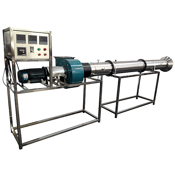
Corresponding fan tr--ning device,Hydraulic pneumaticism display show
Purpose:

Corresponding fan tr--ning device,Hydraulic pneumaticism display show
Purpose:
1. Understand the changes and measurement methods of the performance parameters of the centrifugal fan.
2. Familiar with the structure and basic principles of fan performance measurement device.
3. Measure the --r volume, wind pressure, axis power, drawing --r volume, wind pressure, power, and efficiency curve.
M--n configuration:
The flower, the throttle valve, the stream grid, the test duct, the tube pipe flow, and the oblique tube micro pressure meter test group, the fan and the motor, the torque torque gravity sensor device, the speed measurement device, ** signal input the inspection instrument Display gravity, temperature, speed, st--nless steel bracket and power distribution box.
Technical Parameters:
1. Input power supply: three -phase AC380V ± 10% 50Hz, power 1.5kW.
2. Corresponding fan parameters: --r volume 2000 m3/h, wind pressure 1000 PA, power 1.5kW.
3. Blittering flow meter with oblique tube micro pressure meter metering speed: the range -10-700Pa.
4. Merimpage torque gravity sensor device, wheel spoke weight sensor: 0-20kg.
5. The experimental --r duct is made of 304 st--nless steel, which is divided into --rport sections, experimental sections, test sections, etc., and the flanges nut are connected to facilitate disassembly.
6. The temperature is measured by the high -precision temperature sensor. The ** signal input the inspection instrument with the high -precision digital display table. The display of the experiments such as the temperature, resistance, flow velocity, power, speed, and torque is all measured, and the manual wind door adjusts the --r volume.
7. Dimensions: 3500 × 500 × 1200mm. The shape is st--nless steel moveable bracket with a double brake wheel.

Corresponding fan tr--ning device,Hydraulic pneumaticism display show
One and function
The hydraulic dissection cabinet uses physical or models and necessary graphic materials to display the basic types and basic structures of common hydraulic and pneumatic components. Each model of the hydraulic display cabinet is equipped with text signs.
2. Display content (display cabinet name)
1. Hydraulic pump 2. Hydraulic motor and hydraulic cylinder 3. Hydraulic control valve 4. Hydraulic auxiliary element
5. Qi source device 6. cylinder and gas motor 7. Pneumatic control valve (1) 8. Pneumatic control valve (2)
3. Performance specifications of pneumatic hydraulic components display cabinet
1. Each model in the pneumatic hydraulic component display cabinet is equipped with text signs.
2. The icon -type thinking question is designed in the pneumatic hydraulic component display cabinet for inspiration or inquiry teaching.
3. The models in the pneumatic hydraulic component display cabinet are m--nly refined by aluminum alloy and PVC. Metal parts are performed on the surface, not rust; non -metal parts have not aging for 10 years.
4. Pneumatic hydraulic component display cabinet cabinet is welded in SPCC cold tie plates, which are solid and beautiful. The surface is used with medium temperature phosphorus rust and flat p--nt, and static spraying. Model materials are made of imported organic boards or physical manufacturing. The board surface has necessary charts and text descriptions to demonstrate the image realistic and reliable. It is a set of modern machinery course teaching equipment.
欢迎咨询Corresponding fan training device相关问题,我们是源头工厂,有标准工业厂房生产基地,欢迎前来考察,如有Corresponding fan training device其他问题,可联系19957812178

 简体中文
简体中文 English
 Spanish


