


 简体中文
简体中文 English
 Spanish


Modern factories (especially large enterprises) have high power supply load density, complex power supply methods, high reliability requirements, and strict power quality requirements. They also require higher flexibility to adapt to the increasing power supply loads and power supply network upgrades. In response to this situation, integrating comprehensive automation technology into the factory power supply system has become an inevitable trend and development direction.
"Factory Power Supply Comprehensive Automation Tr*ning System" is based on the Higher Vocational College's "Factory Electrical Appliances and Power Supply", " Electrical Equipment and Operation and M*ntenance", " Power Supply and Distribution Technology", "Power Supply Network Relay Protection", "Distribution It is a comprehensive tr*ning system designed based on the practical tr*ning teaching requirements of courses such as "Power System Automation" and "Distribution Network Automation Technology" and combined with the practical application and development of factory power supply systems.
2. Characteristics
Comprehensiveness: Clearly reflects the primary and secondary parts of a typical factory power supply system, using a variety of electrical equipment that is actually used in factory power supply. Be able to meet the practical skill tr*ning requirements for power reception, transmission, distribution, control, and protection of the factory power supply system;
Advancedness: Comprehensive related technologies of microcomputer functional detection and control such as microcomputer relay protection, power measurement, PLC and industrial control configuration, using hierarchical distributed control method to form a comprehensive automated experiment integrating control, protection, measurement and signal. platform;
Practicality: The system has clear structure, flexible operation and reliable operation.
3. Technical performance
1. Input power supply: three-phase four-wire AC380V±10% 50±2%Hz;
2. Overall machine capacity: ≤3kVA;
3. The tr*ning platform is made of iron with matte dense gr*n spray and aluminum panel;
4. Two communication interfaces: RS-485 and Ethernet; standard MODBUS communication protocol;
5. Accuracy of measuring components of microcomputer protection device: scale error: no more than 1%; measurement current: 0.2 level; bus voltage: 0.2 level; output accuracy: 0.2 level; frequency: 0.01Hz; P, Q, COSΦ; 0.5 level; communication Resolution: no greater than 1ms.
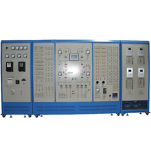
6. The practical tr*ning system consists of four parts: the m*n wiring simulation screen of the power supply and distribution system, the metering cabinet, the control cabinet, and the monitoring software.
7. The practical tr*ning system can simulate the power supply and distribution system of a medium-sized factory. It adopts a control panel structure and the primary m*n wiring is printed on the aluminum panel. It is composed of 35 kV and 10kV, two different voltage levels. The entire system has two 35kV incoming lines, one of which is a normal power supply and the other is a backup, automatically switching through the standby and automatic switching; the 35kV bus outlet has two branches, one is for transmission In other branches, an incoming power supply 1 is reduced by the m*n down-converter to a 10kV bus for local use; in order to ensure the reliability of power supply, an additional power supply is added as an incoming power supply 2 for the 10kV bus. Incoming power supply 1 and incoming power supply 2 are mutually dark backup, supplying power to the 10kV Section I busbar and the 10kV Section II busbar respectively. The two can also be automatically switched through backup and automatic switching. In order to ensure the reliability of the primary line power supply, microcomputer automatic switching, microcomputer line and microcomputer transformer protection are configured; in order to ensure the stable operation of the high-voltage motor, high-voltage motor protection is configured; in order to improve the quality of power consumption, a reactive power compensation device is configured; In order to realize automatic control, a PC and a PLC controller are configured to realize the "four remote" functions of the entire system.
8. The metering cabinet includes: three pointer-type AC voltmeters (accuracy level 1.0, range: 0~500V); three pointer-type AC ammeters (accuracy level 1.0, range: 0~5A); pointer-type three-phase active power meter and three-phase reactive power meter each; electronic active and reactive combined energy meter (1 piece): measurement current: 0.2 level; bus voltage: 0.2 level; output accuracy: 0.2 level; frequency: 0.01HZ; P, Q , COSΦ; level 0.5; communication resolution: no more than 1ms; three-phase intelligent acquisition module (3 pieces): measurement accuracy: 0.2% for current and voltage, 0.5% for other electricity; with RS-485 communication interface; digital electric stopwatch ( 1 piece): Measuring range 0.0001S-9999.9S, measurement error ≤±5×10⁻⁵×range ±1 mantissa digit, with two functions: continuous and touch. Adapt to empty contacts or 5V-250V positive polarity electrical signals. Continuous manual reset, touch-sensitive manual reset, or automatic reset with the measurement signal.
9. The control cabinet includes: microcomputer line protection device (1 piece): with three-stage overcurrent protection, low-voltage blocking current protection, single-phase grounding protection, inverse time overcurrent protection, acceleration before overcurrent, acceleration after overcurrent, and overlap. Gate and other functions; Microcomputer motor protection device (1 piece): It has functions such as current instant break, overcurrent, current inverse time limit, zero sequence overcurrent protection, negative sequence current protection and low voltage protection; Microcomputer transformer protection device (1 piece): It has the functions of current quick-break, over-current, current inverse time limit, zero-sequence over-current protection, negative-sequence current protection and low-voltage protection; microcomputer reactive power compensation device (1 piece): can automatically track the power factor of the grid and control the input of the capacitor bank switching, with manual and automatic switching functions. Phase-separation compensation is carried out according to the reactive power of the transformer, and the capacitor banks work cyclically so that each capacitor group is evenly put into operation, thereby reducing power loss and voltage loss and improving the efficiency of the equipment; microcomputer-equipped automatic switching device (1): There is progress Line backup and bus tie backup modes are optional. When the m*n incoming power supply simulates a fault and loses power, the backup automatic switching device can automatically transfer the backup incoming power to the working bus to ensure the load connected to the working bus. It can still work normally and improve the reliability and stability of power supply. At the same time, it has an adaptive function. When the m*n incoming line power is detected to be restored, the backup incoming line circuit breaker will be automatically opened and the m*n incoming line will be closed with a delay to realize the automatic switching and put-in process when the m*n incoming line voltage is restored; at the same time, all microcomputers are required The protection devices all use TI's high-performance DSP as the control core chip to collect the current, voltage and input and output switching values of the external system and send them to the liquid crystal display. It has fault recording function and can display fault waveform.
Peak harmonic comprehensive protector (2 pieces): Using four-star connection method, it can greatly reduce phase-to-phase overvoltage and greatly improve the reliability of protection. The combined structure of zinc oxide nonlinear resistor and high-energy silicon carbide realizes complementary advantages and improves the service life of the product. The voltage impact coefficient is 1, and the discharge voltage value is equal under various voltage waveforms and is not affected by various operating overvoltage waveforms. The overvoltage protection value is accurate and the protection performance is excellent. The protection threshold voltage is low and the protection effect is good. For example, in a 400V system, the protection voltage can be as low as 430V. As long as it exceeds 430V, various interference overvoltages can be well filtered out; (peak harmonic comprehensive protector needs to be provided National invention patent certificate and type inspection report, prototype provided on site).
10. The upper computer has monitoring software. The monitoring host and on-site intelligent equipment use the RS485 bus and the Modbus-RTU protocol to build the underlying monitoring network. It m*nly realizes the following functions: 1. Configure the primary power supply and distribution system and display changes in the m*n wiring in real time; 2. Real-time collection, display, and storage of various power parameters; 3. Generate real-time and Historical curves and reports are used to facilitate experimenters to compare and analyze experimental data; 4. Monitor the position of each circuit breaker and the protection action outlet status; be able to control the tripping/closing of transmission line circuit breakers; 5. Realize voltage control based on the collected bus power , Automatic adjustment of reactive power.
11. The PLC adopts Schneider PLC host.
12. Teaching software
1. Electrical safety and electric shock first *d simulation teaching software
The software uses a combination of two-dimensional and three-dimensional virtual images to teach students the safety and first *d methods of using electricity. The software includes single-phase electric shock, two-phase electric shock, step electric shock, low-voltage electric shock first *d, high-voltage electric shock first *d, artificial respiration first *d, Principles of hand-holding breathing rescue method, chest cardiac compression and other protective methods are expl*ned and taught. Principles of single-phase electric shock are divided into rep*ring live disconnection, rep*ring socket electric shock, and outdoor electric shock. The teaching of low-voltage electric shock and high-voltage electric shock m*nly expl*ns and demonstrates to students how to rescue people who are suffering from low-voltage electric shock or high-voltage electric shock. Artificial respiration rescue method, hand-holding breathing rescue method, and chest cardiac compression rescue method are demonstrated using 3D virtual simulation technology. After rendering and Polish it to make the model look like the real part and look realistic. Through practical tr*ning, students can be educated on the safe use of electricity in the tr*ning room, improve students' safety awareness, and enable students to learn some self-rescue methods, so that students can take cert*n safety measures to protect themselves when encountering danger, and become familiar with various Causes of electrical accidents and practical measures to deal with them to reduce the occurrence of electrical accidents.
2. M*ntenance of electricians , electronic motors and vocational qualification tr*ning assessment simulation software
This software is in apk format and can be used on PC or mobile. This software can set faults manually or automatically. This software can manually set fault points through the green box in the circuit diagram (you can set up to 39 fault points), you can also automatically set one random fault point, two random fault points, three random fault points, four random fault points, and five random fault points through the system. It has functions such as toolbox, component library, magnifying glass, circuit diagram, etc. You can choose a multimeter for testing through the toolbox, select appropriate components through the component library, and clearly understand each component and circuit through the magnifying glass. This software allows students to understand the working principle and circuit structure of the motor star-delta start control circuit through the setting of faults in the motor star-delta start control circuit and various investigations.
3. Virtual spectrum analyzer, logic analyzer, oscilloscope, and three-meter simulation software:
This software is in apk format and can be used on PC or mobile terminals. The functions of this software are: resistance measurement, AC voltage measurement (measuring transformer, if the multimeter burns out when measuring the transformer, black smoke will emit prompts and can reset the multimeter), determine the polarity of the transistor, measure the DC voltage (the light turns on when the ammeter is turned on), measure the DC current, and determine the quality of the capacitor. This software can drag the red and black pen tips at will. When the two pen tips are dragged and positioned on the object to be measured, a red circle will be displayed. If the positioning is not accurate, no red circle will be displayed, and when incorrect operations are performed (such as the wrong range selected, If the measured data is wrong, etc.), the meter pointer will not respond, prompting errors and re-measurement, etc. This multimeter can select AC voltage gear, DC voltage gear, resistance gear, current gear, resistance adjustment to 0, and can enlarge the display data. Clearly view the measured data size. Students can learn the correct use of multimeters through this software.
4. Microcontroller , PLC programmable design and control virtual simulation software:
This software is developed based on unity3d and has built-in experimental steps, experimental instructions, circuit diagrams, component lists, connection lines, power on, circuit diagrams, scene reset, return and other buttons. After the connections and codes are correct, you can start/stop, The forward movement and reverse movement buttons operate the 3D machine tool model to move. In the connected line state, the 3D machine tool model can be enlarged/reduced and translated.
1. Relay control: Read the experiment instructions and enter the experiment. By reading the circuit diagram, select the relays, thermal relays, switches and other components in the component list and drag and drop them into the electrical cabinet. The limiters are placed in the three-dimensional On the machine tool model, you can choose to cover it, and some component names can be renamed. Then click the Connect Line button to connect terminals to terminals. After successfully connecting the machine tool circuit, choose to turn on the power and proceed. If the component or line An error box will pop up if there is a connection error, and the scene can be reset at any time.
2. PLC control: The experiment is the same as relay control, with the addition of PLC control function. After the connection is completed, enter the program writing interface through the PLC coding button, and write two programs, forward and reverse, with a total of 12 ladder diagram symbols. The writing is completed. Finally, select Submit for program verification. After the verification is successful, turn on the power for operation. Error boxes will pop up for component, line connection, and code errors, and the scene can be reset at any time.
3. Single-chip microcomputer control: The experiment is the same as relay control, with the addition of single-chip microcomputer control function. After the connection is completed, enter the programming interface through the C coding button, enter the correct C language code, and after successful submission and verification, turn on the power for operation, components, lines If there are connection or code errors, an error box will pop up, and the scene can be reset at any time.
4. Practical tr*ning projects
1. Understanding of factory power supply electrical wiring diagram
(1) Understanding of the factory power supply primary electrical wiring simulation diagram
(2) Factory power supply secondary control loop wiring and signal loop tr*ning
(3) Wiring method of voltage and current transformers
(4) Factory power supply switching operation
2. Factory automation equipment tr*ning
(1) Preparatory investment conditions test
(2) Incoming line backup (explicit backup) and adaptive
(3) Bus joint backup (dark backup) and adaptive
(4) Cognition of reactive power compensation devices
(5) Manual/automatic power factor compensation
(6) Line reactive power control
(7) VQC voltage reactive power control
3. Microcomputer relay protection of high-voltage lines in factories
(1) Simulate the normal, maximum and minimum operating modes of the system
(2) Analog system short circuit
(3) Correct operation of electric stopwatch
(4) Microcomputer line protection device parameter setting operation
(5) Line non-time-limited current quick-break protection
(6) The line has time-limited current quick-break protection
(7) Line fixed time overcurrent protection
(8) Line inverse time overcurrent protection
(9) Line current and voltage ch*n protection
(10) Ground protection of lines
4. Relay protection of high-voltage motors
(1) Frequency converter parameter tuning operation
(2) Frequency converter open-loop speed regulation
(3) Starting method of three-phase asynchronous motor
(4) Microcomputer motor protection device parameter setting operation
(5) Motor quick-break protection
(6) Inverse time overcurrent protection of motor
(7) Low voltage protection of motor
(8) Ground protection of motor
5. Transformer microcomputer relay protection
(1) Transformer current quick-break protection
(2) Transformer overcurrent protection
(3) Transformer gas protection
(4) Transformer overload protection
6. Overall monitoring and comprehensive automation
(1) SCADA monitoring
(2) Line fault location, alarm and removal
(3) Power curve analysis and reports
Hot-selling product: Electrician tr*ning bench
欢迎咨询YLGDX-02 Factory Power Supply Comprehensive Automation System Experimental Device相关问题,我们是源头工厂,有标准工业厂房生产基地,欢迎前来考察,如有YLGDX-02 Factory Power Supply Comprehensive Automation System Experimental Device其他问题,可联系19957812178
