


 简体中文
简体中文 English
 Spanish


Equipment entrances are equipped with leakage protectors.
The control power supply of the entire experimental system (including the relay auxiliary voltage) adopts a DC 24V power supply within the safe voltage. The experimental signals are required to be output in accordance with the secondary standards of the power system , and the output power is strictly controlled to eliminate the risk of electric shock.
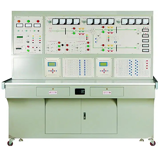
1. Power automation and relay protection comprehensive experimental system
The power automation and relay protection comprehensive experimental system provides a typical m*n system for power system operation and a primary system platform for relay protection experiments.
The experimental bench is composed of a simulated primary m*n system, multi-functional microcomputer protection device, conventional relays, secondary electrical control, etc.
Multifunctional microcomputer protection device:
The multi-functional microcomputer protection device can be used in various relay protection experiments and can also be used as a line protection device in power system experiments.
Requirements include the following:
10kV feeder microcomputer protection device module
35kV line microcomputer device module
110kV line group microcomputer protection device module
Transformer m*n protection device module
Transformer backup protection device module
Capacitor microcomputer protection device module
Motor microcomputer protection device module
Generator differential protection device module
Generator backup protection device module
Digital relay modules such as digital current relays, digital voltage relays, digital power direction relays, digital differential relays, digital impedance relays, and digital inverse time current relays can be flexibly implemented by selecting different functional modules through the menu.
In order to facilitate the experimental wiring, the voltage and current input terminals of the multi-functional microcomputer protection device, the protection tripping and closing signals, and the circuit breaker trip and closing status signals have been introduced to the experimental bench panel inside. Since the wiring of line protection, transformer m*n protection and backup protection are different, different protection terminal areas are provided on the panel.
Provide supporting microcomputer protection graphical programming software.
Microcomputer protection graphical programming software is used for online setting and monitoring of microcomputer protection devices, including functions such as communication monitoring, reading fixed values, downloading fixed values, reading reports, reading SOE reports, and reading wave recording data. The operation mode of the graphical protection device is consistent with the operation mode of the corresponding multi-functional microcomputer protection device. Through the Ethernet port and the hardware connection of the multi-functional microcomputer protection device, the microcomputer protection device can be synchronously monitored and set synchronously, including 10kV line protection, 35kV line protection, 110kV line protection, transformer m*n protection, transformer backup protection, motor protection, and capacitor protection. , PT protection, backup automatic switching, generator differential protection, generator backup protection, reactive power compensation and other online setting and testing of various device functions. It can monitor, track and record signal data during the running of the program. Use signal recording to obt*n data during program execution, and upload the collected signals to the host for display and analysis. The host computer setting data (such as fixed values, pressure plates, system parameters) can be downloaded to the actual protection device through the Ethernet interface.
2. Conventional relay and secondary control
Include at least
Electromagnetic current relay
Electromagnetic voltage relay
Intermediate relay
Time Relay
Power direction relay
Impedance relay
Differential relay
Flash relay
Signal relay
Reclosing relay
Impact relay
Secondary control loop module
Negative sequence voltage relay
buzzer
indicator light
Adjustable DC power supply
3. Power amplifier device
The technical parameters are as follows:
working environment conditions
Ambient temperature: -10℃~40℃
Relative humidity: 5%~95%
AC power voltage: 220V±10%, 50Hz±1%
Adjustable AC voltage output
Output range: four phases, each phase 0~90V (effective value)
Output power: 30VA per phase
Response speed: <200us
Output voltage accuracy: ≤0.5%
Adjustable AC current output
Output range: six phases, 0~20A per phase (effective value).
Output power: 100VA per phase
Response speed: <200us
4. High-speed digital physical interface box
The high-speed digital physical interface box host has a built-in high-performance CPU and high-speed digital signal processor, a 16-bit DAC module, and a large-size colorful resistive touch screen.
It has built-in multiple characteristic test modules and multiple line models . Model parameters can be modified through the touch screen, and the system operating status can be changed to calculate and output current and voltage signals under different operating statuses. It can be run independently on a stand-alone computer or connected to other computers.
The characteristic test module includes: general characteristic test, impedance relay characteristic test, differential relay characteristic test, inverse time current relay characteristic test and other modules.
Line models include: 10kV/35kV/110kV line model, transformer model, motor protection model, capacitor protection model, generator protection model, etc. Each type of model can save 4 sets of parameters. .
1) Powerful networking function: Multiple high-speed digital high-speed digital physical interface boxes can be networked to form a secondary signal source network. The upper PC computer design configuration and power system analysis and calculation software complete the primary power transmission and distribution network of each voltage level. Real configuration; input the real parameters of the equipment once to complete the system's power flow calculation and short-circuit calculation for any fault occurring at any point in the system; input the transformation ratio of the real current transformer and voltage transformer at each measurement and control point to obt*n The real secondary current and voltage values of the measurement and control point; the measurement and control point installed in the system can synchronously send the real secondary current and voltage analog signals of the measurement and control point to the microcomputer protection hardware platform of the measurement and control point to check the operation of each protection. The primary m*n wiring configured by the configuration software is intuitive and real. By inputting real equipment parameters, the fault type can be set at any point in the system. It is very convenient to perform power flow calculation and short circuit calculation. The microcomputer protection tester synchronously sends out each measurement and control point. secondary current and voltage signals.
2) Communication method: Ethernet communication interface must ensure that the communication rate is not less than 100Mb/s.
3) Parameter indicators:
Including basic configurations such as chassis and CPU board, 1 AO board, 1 DI board, 1 DO board and 1 power board each.
AO board: Each board has 10 channels, common ground output, level range: -10V~+10V, resolution 16bit, absolute accuracy better than 2mV.
DI board: Each board has 12 channels, which can be used for level input or empty node input. Level input: 0V/24V.
DO board: Each board has 8 channels, of which 8 are level inputs, 8 are empty node inputs, and level output: 0V/24V.
3. Experimental projects
(1) Conventional relay experiment
Conventional current relay characteristics experiment
Conventional voltage relay characteristics experiment
Conventional power directional relay characteristic experiment
Conventional differential relay characteristics experiment
Conventional Impedance Relay Characteristics Experiment
time relay experiment
Intermediate relay experiment
Conventional current quick-break protection experiment
Conventional current and voltage ch*n quick-break protection experiment
Signal relay experiment
Negative sequence voltage relay experiment
Composite voltage start-up overcurrent protection experiment
Overvoltage protection experiment
Three-phase primary reclosing device experiment
Acceleration protection experiment before automatic reclosing
Accelerated protection experiment after automatic reclosing
Three-stage current protection experiment for single-sided power supply radiating transmission line
Comprehensive experiment and assessment of overcurrent protection and three-phase automatic reclosing device
(2) Electrical experiments in power plants
Impact relay experiment
Experiment on manual return of central signaling device with repeated movements
Experiment on automatic return of central audio signal device for repeated movements
Circuit breaker control loop experiment with light monitoring
Circuit breaker control loop experiment with light and sound monitoring
Experiment on flash device composed of flash relay
Experiment on circuit breaker control loop equipped with jump blocking relay
(3) Microcomputer protection experiment
1. Digital relay characteristics experiment
Digital current relay characteristics experiment
Digital voltage relay characteristics experiment
Digital power directional relay characteristic experiment
Digital Differential Relay Characteristics Experiment
Digital Impedance Relay Characteristics Experiment
Digital inverse time electrical characteristics experiment
2. 10kV-35kV microcomputer protection comprehensive experiment
Three-stage current protection experiment under maximum and minimum operating modes
10kV line overcurrent protection experiment
35kV line current and voltage interlocking quick-break protection experiment
Dual power supply directional overcurrent protection experiment
Inverse time current protection experiment
Overcurrent protection and acceleration protection before automatic reclosing Experiments
: Over-current protection and accelerated protection experiments after automatic reclosing
Zero-sequence voltage protection experiments
Low frequency load shedding
3. 110kV microcomputer protection comprehensive experiment
110kV line direction circular phase distance protection experiment
110kV line direction circular grounding distance protection experiment
Three-stage distance protection experiment
Zero-sequence current protection experiment
Zero-sequence direction protection experiment
Zero-sequence voltage blocking experiment
Distance protection and automatic reclosing experiment
Zero-sequence current protection and automatic Reclosing experiment
4. Comprehensive experiment on transformer protection
Transformer current quick-break protection experiment
Transformer differential quick-break protection experiment
Transformer ratio braking differential protection experiment
Transformer over-current protection experiment
Transformer low-voltage starting over-current protection experiment
Transformer composite voltage starting over-current protection experiment
Transformer overload protection experiment
Simulate heavy gas alarm and tripping experiments
Simulating light gas alarm experiment
Simulate over-temperature alarm and tripping experiments
Simulated over-temperature alarm experiment
5. Comprehensive experiment on capacitor protection
Capacitor limited time current quick-break protection experiment
Capacitor over-current protection experiment
Capacitor over-voltage protection experiment
Capacitor bus voltage loss protection experiment
6. Comprehensive experiment on motor protection
Motor overcurrent protection experiment
Motor unbalance protection experiment
Motor grounding protection experiment
Motor stall protection experiment
Motor starting time too long protection experiment
Motor low voltage protection experiment
Motor overheating protection experiment
7. Generator differential protection experiment
Generator differential quick-break protection experiment
Generator ratio braking differential protection experiment
Generator simulated over-temperature protection experiment
Generator simulated over-temperature protection experiment
8. Generator backup protection experiment
Generator overcurrent protection experiment
Generator low voltage blocking overcurrent protection experiment
Generator composite voltage blocking overcurrent protection experiment
Generator overvoltage protection experiment
Generator zero sequence overvoltage protection experiment
Generator negative sequence overvoltage protection experiment
Generator low voltage protection experiment
Generator overload protection experiment
Generator simulated over-temperature protection experiment
Generator simulated over-temperature alarm experiment
(4) Power System Analysis Course Experiment
Design and configuration of electrical m*n wiring diagram of power system
Power flow calculation for open power networks
Power flow calculation of ring network
Voltage and power distribution in power grids
Analysis and calculation of asymmetric faults in power systems
Analysis and calculation of three-phase short circuit in power system
Power system power flow analysis experiment
Electric power system short circuit calculation experiment
Hot-selling product: Electrician tr*ning bench
欢迎咨询YLDL-JB power automation and relay protection experimental platform相关问题,我们是源头工厂,有标准工业厂房生产基地,欢迎前来考察,如有YLDL-JB power automation and relay protection experimental platform其他问题,可联系19957812178
