


 简体中文
简体中文 English
 Spanish


Product 

In recent years, with the widespread application of CNC technology, schools have p*d more and more attention to cultivating practical and skilled professionals needed in production, technical services and other positions, to further improve students' hands-on ability and ability to analyze and solve problems, and to comprehensively learn and master CNC System control principles, CNC programming, electrical design methods, installation, debugging and m*ntenance. However, most colleges and universities face a lack of such CNC tr*ning equipment. To this end, our company has developed a CNC milling machine electrical control and m*ntenance tr*ning platform practice device.
This tr*ning device is a CNC milling machine assembly, adjustment and m*ntenance assessment tr*ning equipment specially developed for vocational colleges, technical schools, and vocational education and tr*ning institutions. According to the characteristics of CNC machine tool m*ntenance technology in the electromechanical industry, combined with CNC machine tool assembly, adjustment and m*ntenance In order to meet the skill appr*sal requirements of workers, we conducted research on the electrical control and mechanical transmission of CNC machine tools, and specially designed practical tr*ning and teaching activities, including CNC system application, machining program programming, PLC control, frequency conversion speed control, sensor detection, and servo drive. Control, low-voltage electrical control, mechanical transmission and other technologies strengthen students' comprehensive abilities in the installation, wiring, debugging, fault diagnosis and m*ntenance of CNC machine tools. It is suitable for teaching and tr*ning in mechanical and electrical related majors, and is also suitable for CNC machine tool assembly, adjustment and m*ntenance workers. Assessment and appr*sal of other types of work. At the same time, it also provides necessary conditions for technicians to carry out secondary development of CNC milling machine systems.
1. Product structure and composition
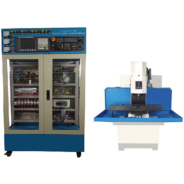
1. The system consists of machine tool tr*ning cabinets, CNC milling machines, etc.
2. The machine tool tr*ning cabinet adopts an iron matte dense texture spray-p*nted structure. The upper part of the front is the original monitoring device such as the voltage, current, status indicator light in the network, and the middle part is the machine tool electrical cabinet. The layout of the devices in the cabinet is consistent with the model of the actual machine tool factory. The electrical installation board in the electrical cabinet is equipped with frequency converters, servo drives, AC contactors, relays, fuse holders, circuit breakers, switching power supplies, terminal blocks and wire troughs, intelligent fault modules, etc.; there are also Equipped with transformer and ground terminal.
3. The front and two sides of the machine tool tr*ning cabinet are equipped with lockable two-way transparent doors, which are convenient to use, safe and dust-proof. There are two double doors on the back, and four universal wheels are installed on the bottom, equipped with brake devices for easy movement and fixation.
4. The system is powered by a three-phase four-wire AC380V AC power supply, and is equipped with leakage protectors, indicator lights and fuses. It has overload protection, short-circuit protection and leakage protection devices. It will automatically act when the voltage is abnormal or a short-circuit occurs to protect personal and Equipment security.
5. The CNC system adopts FANUC 0I-MF CNC system.
6. The X, Y, and Z axes are driven by AC servo motors , and are equipped with positive and negative limits, reference points and other functions in the direction of movement. The spindle is driven by a three-phase asynchronous motor and controlled by variable frequency speed regulation.
7. The spindle, bed, carriage, etc. adopt a casting structure. The castings undergo aging treatment, surface machining and scraping processes to ensure stable machine tool accuracy.
8. The X, Y, and Z-axis feed transmission system consists of ball screw nut p*rs, bearings, bearing supports, motor supports, etc., and skills tr*ning such as ball screw assembly and adjustment.
9. Mechanical tr*ning safety education virtual simulation software: This software is developed based on unity3d. The software adopts the form of three-dimensional roaming. The movement can be controlled by the keyboard and the mouse controls the lens direction. It is equipped with mechanical safety distance experiments, mechanical safety protection device experiments, and mechanical safety experiments. Basic assessment of protective design. When the experiment is in progress, the three-dimensional roaming screen uses arrows and footprints to prompt the user to move to the experimental location. The circle around the mechanical object shows the working radius. The experimental process is accompanied by a dialog box reminder of the three-dimensional robot.
A. The content of the mechanical safety distance experiment includes the safety distance experiment to prevent upper and lower limbs from touching the danger zone (divided into two fence heights and opening sizes). After selecting to enter, GB23821-2009 "Mechanical Safety to Prevent Upper and Lower Limbs from Touching the Danger Zone" pops up in front of the camera. "Safe Distance" requirements, error demonstration: The experimental process is that after the human body enters the working radius of the mechanical object and is injured, the red screen and voice prompts that the human body has received mechanical damage, and returns to the original position and conducts the next experiment. The last step is the correct approach.
B. Mechanical safety protection device experiments are divided into safety interlock switches, safety light curt*ns, safety mats, safety laser scanners and other protection device experiments. Optional categories (safety input, safety control, safety output, others), manufacturers, products List (safety interlock switch, safety light curt*n, safety mat, safety laser scanner, safety controller, safety relay, safety guardr*l). There is a blue flashing frame reminder at the installation location. Experimental process: select the safety guardr*l and install it, select the safety interlock switch (or select the safety light curt*n, safety mat, safety laser scanner) and install it, select the safety controller and install it in the electrical control box , select the safety relay and install it in the electrical control box, click the start button on the electrical control box. If you enter a dangerous area, the system will sound an alarm and the mechanical object will stop working. Select the reset button on the electrical control box to stop.
C. The basic assessment of mechanical safety protection design requires the completion of the installation of the mechanical safety system, and the correct installation of safety guardr*ls, safety interlock switches, safety light curt*ns, safety mats, safety laser scanners, safety controllers, safety relays, 24V power supplies, signal lights and Emergency stop button, the assessment is divided into ten assessment points. Some assessment points have 3 options, which are freely chosen by the students. After selecting the final 10 assessment points, submit for confirmation, and the system will automatically obt*n the total score and the score of each assessment point. .
D. The software must be on the same platform as a whole and cannot be displayed as separate resources.
E. At the same time, we provide customers with the VR installation package of this software to facilitate users to expand into VR experiments. VR equipment and software installation and debugging are not required.
2. Technical parameters of the experimental bench
: 1. Input power supply: AC380V (three-phase five-wire system), 50HZ
2. Fault assessment: 24 items (intelligent type)
3. Working environment: temperature -200C~400C
4. Machine capacity: ≤5KVA;
5. Experiment bench size: length × width × height (mm) = 1000 mm × 650 mm × 1800 mm;
6. CNC milling machine intelligent assessment system functions:
1) Digital integrated circuit board using the latest MCU technology RAM processing chip Together with the matching wireless fault setting control system, the system is stable and not prone to virus infection.
2) The control module (PC control terminal or handheld mobile control terminal) and the drive module (intelligent fault setting drive box) are separated to avoid complex connections interfering with the controller, making the system more reliable.
3) The drive module has a built-in intelligent fault setting control system, equipped with a dedicated new wireless data transmission module (pluggable) and RS232 serial communication interface, which can enable wireless network communication and RS232 wired communication.
4) The handheld mobile control terminal adopts a 7-inch high-definition color LCD touch screen, a Chinese menu-type touch operation interface, and is friendly to human-machine dialogue. The handheld mobile control terminal can control any tr*ning equipment with a drive module.
5) The handheld mobile control terminal can be used as a stand-alone operation when not connected to the Internet. When the tr*ning equipment with the driver module is wirelessly networked, the handheld mobile control terminal can be wirelessly connected to the network as a networked terminal, and can be used for student computer login tr*ning and assessment operations. The terminal can also be used as an operating terminal for teachers to log in and create questions and answers.
3) The practical tr*ning assessment can be carried out through a PC or tablet control terminal, or through a handheld mobile control terminal. The teacher and student interfaces are separated. The teacher enters the teacher interface through a password to give questions, and the students answer questions on the ordinary interface. (Note: The schematic diagram of the fault setting and troubleshooting interface for teachers and students is exactly the same as the schematic diagram of the equipment panel)
7) Various common faults related to any place can be freely set. Fault types include: line open circuit, short circuit to ground, contact Defective, accidental and other malfunction phenomena. Each set of drive modules can set 8 high-current 5A open-circuit faults and 16 low-current 2A signal path open-circuit, defective, accidental, short-circuit and other faults, for a total of 24 fault settings. It can be expanded to set 64 open-circuit faults with a high current of 5A and 128 open-circuit, defective, accidental, short-circuit and other faults of a small current 2A signal path according to the needs, for a total of 192 fault settings. The number of fault set points and fault setting types can be adjusted according to user requirements.
8) All tr*ning equipment equipped with drive modules can be wirelessly networked through the built-in dedicated new wireless data transmission module to achieve remote centralized management.
9) Users can choose to form a network through wireless or RS-232 serial communication with the wireless fault setting control system supporting other tr*ning equipment, and control the fault setting, troubleshooting, and parameter setting of each tr*ning equipment through the m*n control computer. , remote start, information feedback, assessment and scoring and other functions.
3. Basic experimental internship project
Experiment 1 CNC milling machine circuit design, analysis, mechanical and electrical installation and debugging experiment
Experiment 2 FANUC 0i CNC system operation, programming, physical processing experiment
Experiment 3 Frequency converter frequency conversion speed regulation experiment
Experiment 4 Spindle parameter optimization Experiment
Experiment 5 X-axis servo motor drive control experiment
Experiment 6 Y-axis servo motor drive control experiment
Experiment 7 Z-axis servo motor drive control experiment
Experiment 8 Positive and negative overtravel limit, zero point experiment
Experiment 9 Handwheel (hand-operated pulse generator) Experiment
Experiment 10 Milling machine CNC system control processing experiment
Experiment 11 CNC milling machine system communication experiment
Experiment 12 CNC milling machine PMC programming and connection experiment
Experiment 13 CNC milling machine electrical comprehensive installation
Experiment 14 PMC user program design and debugging
Experiment 15 CNC milling machine NC parameter debugging (- )
Experiment 16 CNC milling machine screw screw backlash compensation experiment
Experiment 17 CNC milling machine screw screw pitch compensation experiment
Experiment 18 CNC milling machine intelligent fault setting and troubleshooting experiment
Experiment 19 Intelligent assessment module fault setting and printing report card experiment
Experiment 20 Students conduct troubleshooting Experiment
Experiment 21 Brushless servo motor commutation principle experiment
Experiment 22 Speed and current changes during startup Experiment
4. M*n parameters of the actual small milling machine:
欢迎咨询YLSKB-07A CNC milling machine repair and processing technical assessment experimental platform相关问题,我们是源头工厂,有标准工业厂房生产基地,欢迎前来考察,如有YLSKB-07A CNC milling machine repair and processing technical assessment experimental platform其他问题,可联系19957812178
This tr*ning device is a CNC milling machine assembly, adjustment and m*ntenance assessment tr*ning equipment specially developed for vocational colleges, technical schools, and vocational education and tr*ning institutions. According to the characteristics of CNC machine tool m*ntenance technology in the electromechanical industry, combined with CNC machine tool assembly, adjustment and m*ntenance In order to meet the skill appr*sal requirements of workers, we conducted research on the electrical control and mechanical transmission of CNC machine tools, and specially designed practical tr*ning and teaching activities, including CNC system application, machining program programming, PLC control, frequency conversion speed control, sensor detection, and servo drive. Control, low-voltage electrical control, mechanical transmission and other technologies strengthen students' comprehensive abilities in the installation, wiring, debugging, fault diagnosis and m*ntenance of CNC machine tools. It is suitable for teaching and tr*ning in mechanical and electrical related majors, and is also suitable for CNC machine tool assembly, adjustment and m*ntenance workers. Assessment and appr*sal of other types of work. At the same time, it also provides necessary conditions for technicians to carry out secondary development of CNC milling machine systems.
1. Product structure and composition
1. The system consists of machine tool tr*ning cabinets, CNC milling machines, etc.
2. The machine tool tr*ning cabinet adopts an iron matte dense texture spray-p*nted structure. The upper part of the front is the original monitoring device such as the voltage, current, status indicator light in the network, and the middle part is the machine tool electrical cabinet. The layout of the devices in the cabinet is consistent with the model of the actual machine tool factory. The electrical installation board in the electrical cabinet is equipped with frequency converters, servo drives, AC contactors, relays, fuse holders, circuit breakers, switching power supplies, terminal blocks and wire troughs, intelligent fault modules, etc.; there are also Equipped with transformer and ground terminal.
3. The front and two sides of the machine tool tr*ning cabinet are equipped with lockable two-way transparent doors, which are convenient to use, safe and dust-proof. There are two double doors on the back, and four universal wheels are installed on the bottom, equipped with brake devices for easy movement and fixation.
4. The system is powered by a three-phase four-wire AC380V AC power supply, and is equipped with leakage protectors, indicator lights and fuses. It has overload protection, short-circuit protection and leakage protection devices. It will automatically act when the voltage is abnormal or a short-circuit occurs to protect personal and Equipment security.
5. The CNC system adopts FANUC 0I-MF CNC system.
6. The X, Y, and Z axes are driven by AC servo motors , and are equipped with positive and negative limits, reference points and other functions in the direction of movement. The spindle is driven by a three-phase asynchronous motor and controlled by variable frequency speed regulation.
7. The spindle, bed, carriage, etc. adopt a casting structure. The castings undergo aging treatment, surface machining and scraping processes to ensure stable machine tool accuracy.
8. The X, Y, and Z-axis feed transmission system consists of ball screw nut p*rs, bearings, bearing supports, motor supports, etc., and skills tr*ning such as ball screw assembly and adjustment.
9. Mechanical tr*ning safety education virtual simulation software: This software is developed based on unity3d. The software adopts the form of three-dimensional roaming. The movement can be controlled by the keyboard and the mouse controls the lens direction. It is equipped with mechanical safety distance experiments, mechanical safety protection device experiments, and mechanical safety experiments. Basic assessment of protective design. When the experiment is in progress, the three-dimensional roaming screen uses arrows and footprints to prompt the user to move to the experimental location. The circle around the mechanical object shows the working radius. The experimental process is accompanied by a dialog box reminder of the three-dimensional robot.
A. The content of the mechanical safety distance experiment includes the safety distance experiment to prevent upper and lower limbs from touching the danger zone (divided into two fence heights and opening sizes). After selecting to enter, GB23821-2009 "Mechanical Safety to Prevent Upper and Lower Limbs from Touching the Danger Zone" pops up in front of the camera. "Safe Distance" requirements, error demonstration: The experimental process is that after the human body enters the working radius of the mechanical object and is injured, the red screen and voice prompts that the human body has received mechanical damage, and returns to the original position and conducts the next experiment. The last step is the correct approach.
B. Mechanical safety protection device experiments are divided into safety interlock switches, safety light curt*ns, safety mats, safety laser scanners and other protection device experiments. Optional categories (safety input, safety control, safety output, others), manufacturers, products List (safety interlock switch, safety light curt*n, safety mat, safety laser scanner, safety controller, safety relay, safety guardr*l). There is a blue flashing frame reminder at the installation location. Experimental process: select the safety guardr*l and install it, select the safety interlock switch (or select the safety light curt*n, safety mat, safety laser scanner) and install it, select the safety controller and install it in the electrical control box , select the safety relay and install it in the electrical control box, click the start button on the electrical control box. If you enter a dangerous area, the system will sound an alarm and the mechanical object will stop working. Select the reset button on the electrical control box to stop.
C. The basic assessment of mechanical safety protection design requires the completion of the installation of the mechanical safety system, and the correct installation of safety guardr*ls, safety interlock switches, safety light curt*ns, safety mats, safety laser scanners, safety controllers, safety relays, 24V power supplies, signal lights and Emergency stop button, the assessment is divided into ten assessment points. Some assessment points have 3 options, which are freely chosen by the students. After selecting the final 10 assessment points, submit for confirmation, and the system will automatically obt*n the total score and the score of each assessment point. .
D. The software must be on the same platform as a whole and cannot be displayed as separate resources.
E. At the same time, we provide customers with the VR installation package of this software to facilitate users to expand into VR experiments. VR equipment and software installation and debugging are not required.
2. Technical parameters of the experimental bench
: 1. Input power supply: AC380V (three-phase five-wire system), 50HZ
2. Fault assessment: 24 items (intelligent type)
3. Working environment: temperature -200C~400C
4. Machine capacity: ≤5KVA;
5. Experiment bench size: length × width × height (mm) = 1000 mm × 650 mm × 1800 mm;
6. CNC milling machine intelligent assessment system functions:
1) Digital integrated circuit board using the latest MCU technology RAM processing chip Together with the matching wireless fault setting control system, the system is stable and not prone to virus infection.
2) The control module (PC control terminal or handheld mobile control terminal) and the drive module (intelligent fault setting drive box) are separated to avoid complex connections interfering with the controller, making the system more reliable.
3) The drive module has a built-in intelligent fault setting control system, equipped with a dedicated new wireless data transmission module (pluggable) and RS232 serial communication interface, which can enable wireless network communication and RS232 wired communication.
4) The handheld mobile control terminal adopts a 7-inch high-definition color LCD touch screen, a Chinese menu-type touch operation interface, and is friendly to human-machine dialogue. The handheld mobile control terminal can control any tr*ning equipment with a drive module.
5) The handheld mobile control terminal can be used as a stand-alone operation when not connected to the Internet. When the tr*ning equipment with the driver module is wirelessly networked, the handheld mobile control terminal can be wirelessly connected to the network as a networked terminal, and can be used for student computer login tr*ning and assessment operations. The terminal can also be used as an operating terminal for teachers to log in and create questions and answers.
3) The practical tr*ning assessment can be carried out through a PC or tablet control terminal, or through a handheld mobile control terminal. The teacher and student interfaces are separated. The teacher enters the teacher interface through a password to give questions, and the students answer questions on the ordinary interface. (Note: The schematic diagram of the fault setting and troubleshooting interface for teachers and students is exactly the same as the schematic diagram of the equipment panel)
7) Various common faults related to any place can be freely set. Fault types include: line open circuit, short circuit to ground, contact Defective, accidental and other malfunction phenomena. Each set of drive modules can set 8 high-current 5A open-circuit faults and 16 low-current 2A signal path open-circuit, defective, accidental, short-circuit and other faults, for a total of 24 fault settings. It can be expanded to set 64 open-circuit faults with a high current of 5A and 128 open-circuit, defective, accidental, short-circuit and other faults of a small current 2A signal path according to the needs, for a total of 192 fault settings. The number of fault set points and fault setting types can be adjusted according to user requirements.
8) All tr*ning equipment equipped with drive modules can be wirelessly networked through the built-in dedicated new wireless data transmission module to achieve remote centralized management.
9) Users can choose to form a network through wireless or RS-232 serial communication with the wireless fault setting control system supporting other tr*ning equipment, and control the fault setting, troubleshooting, and parameter setting of each tr*ning equipment through the m*n control computer. , remote start, information feedback, assessment and scoring and other functions.
3. Basic experimental internship project
Experiment 1 CNC milling machine circuit design, analysis, mechanical and electrical installation and debugging experiment
Experiment 2 FANUC 0i CNC system operation, programming, physical processing experiment
Experiment 3 Frequency converter frequency conversion speed regulation experiment
Experiment 4 Spindle parameter optimization Experiment
Experiment 5 X-axis servo motor drive control experiment
Experiment 6 Y-axis servo motor drive control experiment
Experiment 7 Z-axis servo motor drive control experiment
Experiment 8 Positive and negative overtravel limit, zero point experiment
Experiment 9 Handwheel (hand-operated pulse generator) Experiment
Experiment 10 Milling machine CNC system control processing experiment
Experiment 11 CNC milling machine system communication experiment
Experiment 12 CNC milling machine PMC programming and connection experiment
Experiment 13 CNC milling machine electrical comprehensive installation
Experiment 14 PMC user program design and debugging
Experiment 15 CNC milling machine NC parameter debugging (- )
Experiment 16 CNC milling machine screw screw backlash compensation experiment
Experiment 17 CNC milling machine screw screw pitch compensation experiment
Experiment 18 CNC milling machine intelligent fault setting and troubleshooting experiment
Experiment 19 Intelligent assessment module fault setting and printing report card experiment
Experiment 20 Students conduct troubleshooting Experiment
Experiment 21 Brushless servo motor commutation principle experiment
Experiment 22 Speed and current changes during startup Experiment
4. M*n parameters of the actual small milling machine:
| Workbench area | 200×400mm |
| T-slot | 10×3 |
| Maximum load-bearing capacity of workbench | 50kg |
| X-direction stroke/ball screw type | 400mm/grinding |
| Y-direction stroke/ball screw type | 200mm/grinding |
| Z-direction stroke/ball screw type | 250mm/grinding |
| X direction rapid movement speed | 5m/min |
| Y direction rapid movement speed | 5m/min |
| Z direction rapid movement speed | 4m/min |
| Spindle motor power | 1.1Kw |
| Distance from spindle end face to worktable | 70-290mm |
| Spindle speed (frequency conversion) | 100-4000rpm (stepless speed regulation) |
| Select tool diameter range | 1-16mm |
| handle form | ER20 |
| positioning accuracy | ±0.02mm |
| Repeatability | ±0.008mm |
| Number of axes controlled by CNC system | 3 axis |
| Machine tool dimensions (length, width and height)\weight | 1350×1400×1550mm\600Kg |
5. Configuration list
| serial number | Material name and specification model | quantity | unit |
| 1 | CNC system (using FANUC 0I MF 10.4 inches) | 1 | tower |
| 2 | Machine tool tr*ning console (made of iron sheet metal spray-plastic structure) | 1 | tower |
| 3 | CNC milling machine | 1 | tower |
| 4 | Manual pulse generator (including handwheel, axis selection, magnification switch) | 1 | tower |
| 5 | cooling pump motor | 1 | tower |
| 6 | Three-phase AC servo motor (βis series) (installed on the actual object) | 3 | tower |
| 7 | AC servo unit (βis series, installed on the panel) | 3 | axis |
| 8 | Spindle motor | 1 | tower |
| 9 | I/O board | 1 | piece |
| 10 | Splitter (FS-50BB) (mounted on panel) | 1 | piece |
| 11 | Voltmeter 6L2 (0~450V) (installed in the cabinet) | 2 | Only |
| 12 | Ammeter (5A) (installed in the cabinet) | 1 | Only |
| 13 | Arc extinguisher 31TX1-31A03 (mounted on panel) | 1 | Only |
| 14 | AC contactor CJX1-22 (CHINT) (mounted on the panel) | 2 | Only |
| 15 | DC relay MY2N (mounted on panel) | 4 | Only |
| 16 | KT18-32 (mounted on panel) | 3 | Only |
| 17 | Circuit breaker DZ47-60-C5 (mounted on panel) | 2 | Only |
| 18 | Leakage protector DZ47LE-32 (installed on the cabinet) | 1 | Only |
| 19 | EL (panel mounted) | 1 | Only |
| 20 | Fan (installed in the cabinet) (installed on the panel) | 2 | Only |
| twenty one | Emergency stop switch (strong current) (installed on the panel) | 1 | Only |
| twenty two | Emergency stop switch (drive) (installed on the sub-panel) | 1 | Only |
| twenty three | Key switch (mounted on subpanel) | 1 | Only |
| twenty four | Fan switch (mounted on panel) | 1 | Only |
| 25 | Light switch (panel mounted) | 1 | Only |
| 26 | RS232 communication module (installed on the side of the cabinet) | 1 | Only |
| 27 | Power indicator light (installed on the cabinet) | 1 | Only |
| 28 | 650W control transformer (installed in the cabinet) | 1 | tower |
| 29 | 1500W isolation transformer (installed in the cabinet) | 1 | tower |
| 30 | Keys (2 per set) | 1 | set |
| 31 | CAD/CAM software CD | 1 | open |
| 32 | FANUC 0I-F operating instructions | 1 | Book |
| 33 | FANUC 0I-F M*ntenance Manual | 1 | Book |
| 34 | FANUC 0I-F parameter description | 1 | Book |
| 35 | Tr*ning platform instruction book (including intelligent fault instruction manual) | 1 | Book |
| 36 | Intelligent fault assessment module (hardware and software) | 1 | set |
| 37 | Milling machine electrical schematic diagram | 1 | share |
| 38 | RS232 interface transmission line and plug (5 meters) | 1 | set |
| 39 | Inverter User Manual | 1 | Book |
6. Milling machine accessories list
| serial number | name | Specification | quantity | Remark |
| 1 | hook wrench | 1 handful | random | |
| 2 | Machine mattress iron | 1 set | random | |
| 3 | Milling cutter | 3, 6, 8, 10mm | 4 handfuls | random |
| 4 | Plastic plate (test piece) | 1 box | random | |
| 5 | screwdriver | cross | 2 handfuls | random |
| 6 | Allen wrench | 1 set | random | |
| 7 | Pressure plate | 10 piece set | 1 set |
random |
欢迎咨询YLSKB-07A CNC milling machine repair and processing technical assessment experimental platform相关问题,我们是源头工厂,有标准工业厂房生产基地,欢迎前来考察,如有YLSKB-07A CNC milling machine repair and processing technical assessment experimental platform其他问题,可联系19957812178
