


 简体中文
简体中文 English
 Spanish


Product 

In recent years, with the widespread application of CNC technology, schools have p*d more and more attention to cultivating practical and skilled professionals needed in production, technical services and other positions, to further improve students' hands-on ability and ability to analyze and solve problems, and to comprehensively learn and master CNC System control principles, CNC programming, electrical design methods, installation, debugging and m*ntenance. However, most colleges and universities face a lack of such CNC tr*ning equipment. To this end, our company has developed the principle of CNC lathe electronic control system and the debugging and m*ntenance experimental bench practice device. Using this device can enable students to master CNC lathe system control principles, electrical design methods, component selection, lathe electrical installation and debugging, fault diagnosis and m*ntenance, part programming and graphic simulation processing processes and many other experimental contents, reaching the industrial production site Internship effect. The device adopts an open structure and modular design, and can be used for teaching, course design, graduation projects and practical tr*ning. It is conducive to improving students' ability to design CNC machine tool electrical control systems and diagnose CNC equipment faults, maximizing the number of tr*nees. Adapt and meet market needs to the maximum extent possible. This device can also help scientific research and technical personnel further understand the structure of CNC lathes, and also provides necessary conditions for technical personnel to carry out secondary development of CNC lathe systems. The m*n components of the experimental device are all industrial control products.
1. The tr*ning bench is equipped with: 1 four-station electric tool holder, 1 set of spindle motor and encoder, 1 cooling pump, 2 servo motors, 1 lathe, X and Z limit switches and machine tool zero point and lubrication system etc.
2. Technical parameters of the experimental bench:
1. Input power supply: AC380V (three-phase five-wire system), 50HZ
2. 36 fault assessment items
3. Working environment: temperature -200C ~ 400 C
4. Machine capacity: ≤8kVA;
5. Experimental bench size: length × width × height (mm) = 1000 mm × 650 mm × 1800 mm;
6. It has the function of fault diagnosis and m*ntenance assessment of CNC lathes, and can set 36 typical electrical faults of CNC lathes. The assessment system adopts an intelligent assessment method and has the function of networking. Faults can be set through the computer or on the intelligent assessment terminal. Students analyze the fault phenomenon and enter the corresponding fault code on the assessment terminal to troubleshoot. Multiple devices can be connected to the network through the wireless network and the host computer to centrally manage teacher login, student exams, fault question banks, and separate settings. And can analyze, evaluate, archive, and print test results.
3. Product structure and composition
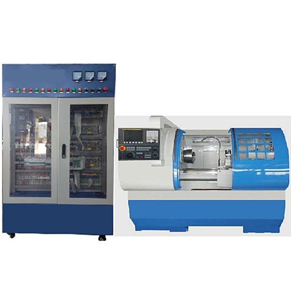
1. The system consists of machine tool tr*ning cabinets, 6432 CNC lathes, etc.
2. The machine tool tr*ning cabinet adopts an iron matte dense texture spray-p*nted structure. The upper part of the front is the original monitoring device such as the voltage, current, status indicator light in the network, and the middle part is the machine tool electrical cabinet. The layout of the devices in the cabinet is consistent with the model of the actual machine tool factory. The electrical installation board in the electrical cabinet is equipped with frequency converters, servo drives, AC contactors, relays, fuse holders, circuit breakers, switching power supplies, terminal blocks and wire troughs, intelligent fault modules, etc.; there are also Equipped with transformer and ground terminal.
3. The front and two sides of the machine tool tr*ning cabinet are equipped with lockable two-way transparent doors, which are convenient to use, safe and dust-proof. There are two double doors on the back, and four universal wheels are installed on the bottom, equipped with brake devices for easy movement and fixation.
4. The system is powered by a three-phase four-wire AC380V AC power supply, and is equipped with leakage protectors, indicator lights and fuses. It has overload protection, short-circuit protection and leakage protection devices. It will automatically act when the voltage is abnormal or a short-circuit occurs to protect personal and Equipment security.
5. The CNC system adopts m*nstream CNC systems from FANUC manufacturers, which can meet the needs of practical tr*ning and teaching of different types of machine tools.
6. The X and Z axes are driven by AC servo motors. They are equipped with positive and negative limit and reference point switches in the direction of movement, and adopt industrial standard travel switches. The spindle is driven by a three-phase asynchronous motor and controlled by variable frequency speed regulation.
7. The X and Z-axis feed transmission systems are composed of ball screw nut p*rs, guide r*ls, bearings, bearing supports, motor supports, etc., and skills tr*ning such as the assembly and adjustment of ball screws.
8. Mechanical tr*ning safety education virtual simulation software: This software is developed based on unity3d. The software adopts the form of three-dimensional roaming, which can control movement through the keyboard and the mouse to control the lens direction. It is equipped with mechanical safety distance experiments, mechanical safety protection device experiments, and mechanical safety experiments. Basic assessment of protective design. When the experiment is in progress, the three-dimensional roaming screen uses arrows and footprints to prompt the user to move to the experimental location. The circle around the mechanical object shows the working radius. The experimental process is accompanied by a dialog box reminder of the three-dimensional robot.
A. The content of the mechanical safety distance experiment includes the safety distance experiment to prevent upper and lower limbs from touching the danger zone (divided into two fence heights and opening sizes). After selecting to enter, GB23821-2009 "Mechanical Safety to Prevent Upper and Lower Limbs from Touching the Danger Zone" pops up in front of the camera. "Safe Distance" requirements, error demonstration: The experimental process is that after the human body enters the working radius of the mechanical object and is injured, the red screen and voice prompts that the human body has received mechanical damage, and returns to the original position and conducts the next experiment. The last step is the correct approach.
B. Mechanical safety protection device experiments are divided into safety interlock switches, safety light curt*ns, safety mats, safety laser scanners and other protection device experiments. Optional categories (safety input, safety control, safety output, others), manufacturers, products List (safety interlock switch, safety light curt*n, safety mat, safety laser scanner, safety controller, safety relay, safety guardr*l). There is a blue flashing frame reminder at the installation location. Experimental process: select the safety guardr*l and install it, select the safety interlock switch (or select the safety light curt*n, safety mat, safety laser scanner) and install it, select the safety controller and install it in the electrical control box , select the safety relay and install it in the electrical control box, click the start button on the electrical control box. If you enter a dangerous area, the system will sound an alarm and the mechanical object will stop working. Select the reset button on the electrical control box to stop.
C. The basic assessment of mechanical safety protection design requires the completion of the installation of the mechanical safety system, and the correct installation of safety guardr*ls, safety interlock switches, safety light curt*ns, safety mats, safety laser scanners, safety controllers, safety relays, 24V power supplies, signal lights and Emergency stop button, the assessment is divided into ten assessment points. Some assessment points have 3 options, which are freely chosen by the students. After selecting the final 10 assessment points, submit for confirmation, and the system will automatically obt*n the total score and the score of each assessment point. .
D. The software must be on the same platform as a whole and cannot be displayed as separate resources.
E. At the same time, we provide customers with the VR installation package of this software to facilitate users to expand into VR experiments. VR equipment and software installation and debugging are not required.
4. Basic experimental internship project
Experiment 1: Power supply control of CNC lathe electrical comprehensive experimental device
Experiment 2: Operation and interface experiment of CNC system
Experiment 3 Frequency converter speed regulation experiment (system stepless speed regulation and frequency converter multi-stage speed control)
Experiment 4 Four-station automatic tool holder experiment
Experiment 5 X-axis servo motor drive control experiment
Experiment 6 Z-axis servo motor drive control experiment
Experiment 7 Experiment on positive and negative overtravel limit and zero point of lathe
Experiment 8 Handwheel (hand-operated pulse generator) experiment
Experiment 9 Experiment on thread processing controlled by lathe CNC system
Experiment 10 CNC lathe system communication experiment
Experiment 11 CNC lathe PMC programming and connection experiment
Experiment 10 2. Comprehensive electrical installation of CNC lathes.
Experiment 13. Design of PMC user program.
Experiment 14. Debugging of PMC user program.
Experiment 15. Debugging of NC parameters of CNC lathe (-).
Experiment 16. Debugging of NC parameters of CNC lathe (2)
Experiment 17. CNC lathe wire Rod Backlash Compensation
Experiment 18 CNC Lathe Screw Pitch Compensation
5. Machine Tool Features:
1. The base of this machine tool is wide and thick, with sufficient weight, low center of gravity and excellent support, which provides a strong guarantee for high-speed and high-precision machining; and for lifting shovels Reasonable arrangements have been made for transportation.
2. The bed and m*n components are made of high-standard Yunnan high-quality cast iron. Through advanced full-resin sand casting technology and long-term treatment, the accuracy and stability of the machine tool structure are greatly improved, adapting to high-speed and high-precision processing. .
3. The key structural parts of the machine tool are processed by large-scale imported high-precision CNC equipment such as pentahedral machining center, gantry guide r*l grinding, special boring and milling horizontal machining, etc., with excellent technology and high precision.
4. The functional components of the machine tool, including the spindle, ball screw, guide r*l, lubrication device, tool holder, coupling, screw bearing, etc., are all imported/domestic famous products, reliable and durable.
5. The guide r*ls of the two-axis feed system adopt super audio quenching technology, which has strong wear resistance and good accuracy retention; the spindle system has an advanced structure, high rotation accuracy, good vibration resistance, and high cutting performance; longitudinal and The transverse direction adopts ball screw transmission; it has excellent dynamic response and low noise of the whole machine.
6. The structure of the ball screw can achieve precise movement and positioning, with low friction, fast speed and long life.
7. The two-axis ball screws are all pre-stretched, which improves the rigidity of the screw and minimizes errors caused by thermal deformation during high-speed operation.
8. The ball screw bearing is an imported special screw bearing, which greatly improves the axial rigidity, precision and impact resistance of the feed shaft.
9. The ball screw and AC servo motor shaft use elastic couplings for gapless direct transmission to ensure accurate positioning of mechanical movement.
10. Equipped with an automatic centralized lubrication system to lubricate the guide r*ls and ball screws regularly and quantitatively. Improved machine tool processing accuracy and service life.
11. The machine tool is equipped with a semi-protective cover, an integral sheet metal protective chassis, and proper water, oil and electrical treatment. The overall structure is novel, beautiful, reliable and practical.
12. An independent cooling water tank is used to facilitate the recovery of iron filings and coolant, and there is no splashing or leakage. This phenomenon provides a strong guarantee for factory management and work area hygiene. Chips can be quickly removed at any time, saving time and manpower.
13. The CNC system and drive unit are mature products of well-known brands; the PLC has been used for many years and is safe and reliable; the electrical design of the machine tool is precise, the process specifications, and the electrical appliances are all well-known domestic brands, with low f*lure rate and durability.
14. The assembly process of the machine tool is exquisite, and the moving parts are corrected by laser interferometer and ball bar, which greatly improves the operating accuracy of the machine tool. The mechanical accuracy is far better than the national standard.
15. The horizontal CNC lathe adopts mechatronics design, with beautiful appearance, reasonable structure, wide range of uses and easy operation. This machine tool can realize automatic control and can complete the processes of turning internal and external circles, end faces, grooving, arbitrary cones, spherical surfaces, metric and inch cylinders, and conical threads of various parts. And equipped with complete S. T. M function can send and receive a variety of signals to control the automatic processing process. The machine tool bed guide r*l adopts super audio quenching technology, which has strong wear resistance and good accuracy retention; the spindle system has an advanced structure, high rotation accuracy, good vibration resistance, and high cutting performance; vertical and horizontal ball screws are used Transmission; excellent dynamic response and low overall machine noise. This machine tool has strong adaptability to the processing of large, medium and small batches, multi-variety and multi-specification parts, especially the processing of conical surfaces, spherical surfaces and other special-shaped parts, which shows its high efficiency, stable and reliable quality. superiority.
6. M*n specifications and parameters of machine tools
7. Configuration list
8. Lathe accessories list
欢迎咨询YLSKB-07B CNC lathe maintenance and processing technology assessment experimental platform相关问题,我们是源头工厂,有标准工业厂房生产基地,欢迎前来考察,如有YLSKB-07B CNC lathe maintenance and processing technology assessment experimental platform其他问题,可联系19957812178
1. The tr*ning bench is equipped with: 1 four-station electric tool holder, 1 set of spindle motor and encoder, 1 cooling pump, 2 servo motors, 1 lathe, X and Z limit switches and machine tool zero point and lubrication system etc.
2. Technical parameters of the experimental bench:
1. Input power supply: AC380V (three-phase five-wire system), 50HZ
2. 36 fault assessment items
3. Working environment: temperature -200C ~ 400 C
4. Machine capacity: ≤8kVA;
5. Experimental bench size: length × width × height (mm) = 1000 mm × 650 mm × 1800 mm;
6. It has the function of fault diagnosis and m*ntenance assessment of CNC lathes, and can set 36 typical electrical faults of CNC lathes. The assessment system adopts an intelligent assessment method and has the function of networking. Faults can be set through the computer or on the intelligent assessment terminal. Students analyze the fault phenomenon and enter the corresponding fault code on the assessment terminal to troubleshoot. Multiple devices can be connected to the network through the wireless network and the host computer to centrally manage teacher login, student exams, fault question banks, and separate settings. And can analyze, evaluate, archive, and print test results.
3. Product structure and composition
1. The system consists of machine tool tr*ning cabinets, 6432 CNC lathes, etc.
2. The machine tool tr*ning cabinet adopts an iron matte dense texture spray-p*nted structure. The upper part of the front is the original monitoring device such as the voltage, current, status indicator light in the network, and the middle part is the machine tool electrical cabinet. The layout of the devices in the cabinet is consistent with the model of the actual machine tool factory. The electrical installation board in the electrical cabinet is equipped with frequency converters, servo drives, AC contactors, relays, fuse holders, circuit breakers, switching power supplies, terminal blocks and wire troughs, intelligent fault modules, etc.; there are also Equipped with transformer and ground terminal.
3. The front and two sides of the machine tool tr*ning cabinet are equipped with lockable two-way transparent doors, which are convenient to use, safe and dust-proof. There are two double doors on the back, and four universal wheels are installed on the bottom, equipped with brake devices for easy movement and fixation.
4. The system is powered by a three-phase four-wire AC380V AC power supply, and is equipped with leakage protectors, indicator lights and fuses. It has overload protection, short-circuit protection and leakage protection devices. It will automatically act when the voltage is abnormal or a short-circuit occurs to protect personal and Equipment security.
5. The CNC system adopts m*nstream CNC systems from FANUC manufacturers, which can meet the needs of practical tr*ning and teaching of different types of machine tools.
6. The X and Z axes are driven by AC servo motors. They are equipped with positive and negative limit and reference point switches in the direction of movement, and adopt industrial standard travel switches. The spindle is driven by a three-phase asynchronous motor and controlled by variable frequency speed regulation.
7. The X and Z-axis feed transmission systems are composed of ball screw nut p*rs, guide r*ls, bearings, bearing supports, motor supports, etc., and skills tr*ning such as the assembly and adjustment of ball screws.
8. Mechanical tr*ning safety education virtual simulation software: This software is developed based on unity3d. The software adopts the form of three-dimensional roaming, which can control movement through the keyboard and the mouse to control the lens direction. It is equipped with mechanical safety distance experiments, mechanical safety protection device experiments, and mechanical safety experiments. Basic assessment of protective design. When the experiment is in progress, the three-dimensional roaming screen uses arrows and footprints to prompt the user to move to the experimental location. The circle around the mechanical object shows the working radius. The experimental process is accompanied by a dialog box reminder of the three-dimensional robot.
A. The content of the mechanical safety distance experiment includes the safety distance experiment to prevent upper and lower limbs from touching the danger zone (divided into two fence heights and opening sizes). After selecting to enter, GB23821-2009 "Mechanical Safety to Prevent Upper and Lower Limbs from Touching the Danger Zone" pops up in front of the camera. "Safe Distance" requirements, error demonstration: The experimental process is that after the human body enters the working radius of the mechanical object and is injured, the red screen and voice prompts that the human body has received mechanical damage, and returns to the original position and conducts the next experiment. The last step is the correct approach.
B. Mechanical safety protection device experiments are divided into safety interlock switches, safety light curt*ns, safety mats, safety laser scanners and other protection device experiments. Optional categories (safety input, safety control, safety output, others), manufacturers, products List (safety interlock switch, safety light curt*n, safety mat, safety laser scanner, safety controller, safety relay, safety guardr*l). There is a blue flashing frame reminder at the installation location. Experimental process: select the safety guardr*l and install it, select the safety interlock switch (or select the safety light curt*n, safety mat, safety laser scanner) and install it, select the safety controller and install it in the electrical control box , select the safety relay and install it in the electrical control box, click the start button on the electrical control box. If you enter a dangerous area, the system will sound an alarm and the mechanical object will stop working. Select the reset button on the electrical control box to stop.
C. The basic assessment of mechanical safety protection design requires the completion of the installation of the mechanical safety system, and the correct installation of safety guardr*ls, safety interlock switches, safety light curt*ns, safety mats, safety laser scanners, safety controllers, safety relays, 24V power supplies, signal lights and Emergency stop button, the assessment is divided into ten assessment points. Some assessment points have 3 options, which are freely chosen by the students. After selecting the final 10 assessment points, submit for confirmation, and the system will automatically obt*n the total score and the score of each assessment point. .
D. The software must be on the same platform as a whole and cannot be displayed as separate resources.
E. At the same time, we provide customers with the VR installation package of this software to facilitate users to expand into VR experiments. VR equipment and software installation and debugging are not required.
4. Basic experimental internship project
Experiment 1: Power supply control of CNC lathe electrical comprehensive experimental device
Experiment 2: Operation and interface experiment of CNC system
Experiment 3 Frequency converter speed regulation experiment (system stepless speed regulation and frequency converter multi-stage speed control)
Experiment 4 Four-station automatic tool holder experiment
Experiment 5 X-axis servo motor drive control experiment
Experiment 6 Z-axis servo motor drive control experiment
Experiment 7 Experiment on positive and negative overtravel limit and zero point of lathe
Experiment 8 Handwheel (hand-operated pulse generator) experiment
Experiment 9 Experiment on thread processing controlled by lathe CNC system
Experiment 10 CNC lathe system communication experiment
Experiment 11 CNC lathe PMC programming and connection experiment
Experiment 10 2. Comprehensive electrical installation of CNC lathes.
Experiment 13. Design of PMC user program.
Experiment 14. Debugging of PMC user program.
Experiment 15. Debugging of NC parameters of CNC lathe (-).
Experiment 16. Debugging of NC parameters of CNC lathe (2)
Experiment 17. CNC lathe wire Rod Backlash Compensation
Experiment 18 CNC Lathe Screw Pitch Compensation
5. Machine Tool Features:
1. The base of this machine tool is wide and thick, with sufficient weight, low center of gravity and excellent support, which provides a strong guarantee for high-speed and high-precision machining; and for lifting shovels Reasonable arrangements have been made for transportation.
2. The bed and m*n components are made of high-standard Yunnan high-quality cast iron. Through advanced full-resin sand casting technology and long-term treatment, the accuracy and stability of the machine tool structure are greatly improved, adapting to high-speed and high-precision processing. .
3. The key structural parts of the machine tool are processed by large-scale imported high-precision CNC equipment such as pentahedral machining center, gantry guide r*l grinding, special boring and milling horizontal machining, etc., with excellent technology and high precision.
4. The functional components of the machine tool, including the spindle, ball screw, guide r*l, lubrication device, tool holder, coupling, screw bearing, etc., are all imported/domestic famous products, reliable and durable.
5. The guide r*ls of the two-axis feed system adopt super audio quenching technology, which has strong wear resistance and good accuracy retention; the spindle system has an advanced structure, high rotation accuracy, good vibration resistance, and high cutting performance; longitudinal and The transverse direction adopts ball screw transmission; it has excellent dynamic response and low noise of the whole machine.
6. The structure of the ball screw can achieve precise movement and positioning, with low friction, fast speed and long life.
7. The two-axis ball screws are all pre-stretched, which improves the rigidity of the screw and minimizes errors caused by thermal deformation during high-speed operation.
8. The ball screw bearing is an imported special screw bearing, which greatly improves the axial rigidity, precision and impact resistance of the feed shaft.
9. The ball screw and AC servo motor shaft use elastic couplings for gapless direct transmission to ensure accurate positioning of mechanical movement.
10. Equipped with an automatic centralized lubrication system to lubricate the guide r*ls and ball screws regularly and quantitatively. Improved machine tool processing accuracy and service life.
11. The machine tool is equipped with a semi-protective cover, an integral sheet metal protective chassis, and proper water, oil and electrical treatment. The overall structure is novel, beautiful, reliable and practical.
12. An independent cooling water tank is used to facilitate the recovery of iron filings and coolant, and there is no splashing or leakage. This phenomenon provides a strong guarantee for factory management and work area hygiene. Chips can be quickly removed at any time, saving time and manpower.
13. The CNC system and drive unit are mature products of well-known brands; the PLC has been used for many years and is safe and reliable; the electrical design of the machine tool is precise, the process specifications, and the electrical appliances are all well-known domestic brands, with low f*lure rate and durability.
14. The assembly process of the machine tool is exquisite, and the moving parts are corrected by laser interferometer and ball bar, which greatly improves the operating accuracy of the machine tool. The mechanical accuracy is far better than the national standard.
15. The horizontal CNC lathe adopts mechatronics design, with beautiful appearance, reasonable structure, wide range of uses and easy operation. This machine tool can realize automatic control and can complete the processes of turning internal and external circles, end faces, grooving, arbitrary cones, spherical surfaces, metric and inch cylinders, and conical threads of various parts. And equipped with complete S. T. M function can send and receive a variety of signals to control the automatic processing process. The machine tool bed guide r*l adopts super audio quenching technology, which has strong wear resistance and good accuracy retention; the spindle system has an advanced structure, high rotation accuracy, good vibration resistance, and high cutting performance; vertical and horizontal ball screws are used Transmission; excellent dynamic response and low overall machine noise. This machine tool has strong adaptability to the processing of large, medium and small batches, multi-variety and multi-specification parts, especially the processing of conical surfaces, spherical surfaces and other special-shaped parts, which shows its high efficiency, stable and reliable quality. superiority.
6. M*n specifications and parameters of machine tools
| Lathe bed form | Integrated bed | |
| Maximum workpiece rotation diameter on the bed | ≥320mm | |
| Maximum workpiece length (center distance) | ≥500mm | |
|
Maximum workpiece processing diameter |
bed frame | ≥320mm |
| Drag strip | ≥165mm | |
| Maximum workpiece processing length | ≥450mm | |
| Spindle head form/taper/taper hole | MT5 | |
| Spindle through hole diameter | ≥Φ60mm | |
| Spindle speed (variable frequency stepless) | ≥50~2500/rpm | |
| Spindle power | ≥4KW | |
| Rapid moving speed X/Z axis | ≥6000/8000mm/min | |
| Maximum stroke of carriage X/Z axis | ≥230/480mm | |
| Electric knife holder form and number of installed knives | ≥Vertical 4 stations | |
| Tool bar cross-section size | ≥20×20mm | |
| Positioning accuracy X/Z axis | ≤0.02/0.03mm | |
| Repeat positioning accuracy X/Z axis | ≤0.01/0.016mm | |
| Workpiece processing accuracy | IT6~IT7 | |
| Workpiece surface roughness | Ra1.6 | |
| Top sleeve inner hole taper | ≥ Mohs No. 4 | |
| Maximum movement of top sleeve | ≥100mm | |
| Maximum horizontal movement | ±10mm | |
| Dimensions | ≥2000×1300×1700mm | |
| Machine tool net weight | ≥1400KG | |
| serial number | Material name and specification model | quantity | unit |
| 1 | CNC system (using FANUC 0I TF) | 1 | tower |
| 2 | Machine tool tr*ning console (made of iron sheet metal spray-plastic structure) | 1 | tower |
| 3 | CK6432 CNC lathe | 1 | tower |
| 4 | Hand pulse generator (FANUC handwheel) (mounted on the panel) | 1 | tower |
| 5 | Four-station tool holder (including wrench) | 1 | set |
| 6 | cooling pump motor | 1 | tower |
| 7 | Three-phase AC servo motor (βIS series) (installed on the physical machine tool) | 2 | tower |
| 8 | AC servo unit (βIS series, installed on the panel) | 2 | tower |
| 9 | X, Z axis positive and negative limits, machine tool zero return switch (installed on the physical machine tool) | 2 | Only |
| 10 | Frequency converter (mounted on panel) | 1 | tower |
| 11 | I/O board (FANUC) | 1 | piece |
| 12 | Splitter (FS-50BB) (mounted on panel) | 1 | piece |
| 13 | Voltmeter 6L2 (0~450V) (mounted on the panel) | 1 | Only |
| 14 | Voltmeter 85L17 (0~450V) (mounted on the panel) | 1 | Only |
| 15 | 24V digital DC voltmeter (mounted on panel) | 2 | Only |
| 16 | Arc extinguisher 31TX1-31A03 (mounted on panel) | 1 | Only |
| 17 | AC contactor CJX1-22 (CHINT) (mounted on the panel) | 4 | Only |
| 18 | DC relay MY2N (mounted on panel) | 6 | Only |
| 19 | KT18-32 (mounted on panel) | 3 | Only |
| 20 | Circuit breaker DZ47-60-C5 (CHINT) (mounted on the panel) | 3 | Only |
| twenty one | Leakage protector DZ47LE-32 (CHINT) (installed on the cabinet) | 1 | Only |
| twenty two | EL (panel mounted) | 1 | Only |
| twenty three | Fan (installed in the cabinet) (installed on the panel) | 1 | Only |
| twenty four | Emergency stop switch (strong current) (installed on the panel) | 1 | Only |
| 25 | Emergency stop switch (drive) (installed on the sub-panel) | 1 | Only |
| 26 | Fan switch (mounted on panel) | 1 | Only |
| 27 | Light switch (panel mounted) | 1 | Only |
| 28 | Power indicator light (installed on the cabinet) | 1 | Only |
| 29 | DC 24V power supply (installed in the cabinet) | 2 | tower |
| 30 | 650W transformer (installed in the cabinet) | 1 | tower |
| 31 | 1500W transformer (installed in the cabinet) | 1 | tower |
| 32 | Keys (2 per set) | 1 | set |
| 33 | CAD/CAM software CD | 1 | open |
| 34 | Inverter User Manual | 1 | Book |
| 35 | FUANC 0I-D User Manual | 1 | Book |
| 36 | FUANC 0I D Service Manual | 1 | Book |
| 37 | FUANC 0I D parameter description | 1 | Book |
| 38 | Tr*ning platform instruction book (including intelligent fault instruction manual) | 1 | Book |
| 39 | CNC lathe fault circuit diagram | 1 | share |
| 40 | Intelligent fault assessment software | 1 | set |
| 41 | RS232 interface transmission line and plug (5 meters) | 1 | set |
| serial number | name | Specification | quantity | Remark |
| 1 | Three jaw chuck | 1 | Already installed on the machine tool | |
| 2 | Chuck positive jaw | 1 p*r | Already installed on the chuck | |
| 3 | Chuck anti-jaw | 1 p*r | random | |
| 4 | Chuck wrench | 1 handful | random | |
| 5 | Tool holder wrench | 1 handful | random | |
| 6 | Machine mattress iron | 6 | random | |
| 7 | dead top | 1 | random | |
| 8 | Knife spacer | 1 box | random | |
| 9 | turning tool | 4 handfuls | random | |
| 10 | T*lstock wrench (dull wrench) | 1 handful | random | |
| 11 | Plastic rod (test piece) | 1 box | random | |
| 12 | screwdriver | cross | 2 handfuls | random |
| 13 | Allen wrench | 1 set | random |
欢迎咨询YLSKB-07B CNC lathe maintenance and processing technology assessment experimental platform相关问题,我们是源头工厂,有标准工业厂房生产基地,欢迎前来考察,如有YLSKB-07B CNC lathe maintenance and processing technology assessment experimental platform其他问题,可联系19957812178
